Chapter 5
5-17
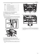
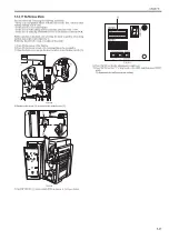
- 4mm for A-configuration, 72.7 +/- 4mm for L-configuration). If the sta-
pling position is out of the specification, go through the procedure again
from step 6).
F-5-74
11) Once the adjustment is complete, press SW385 to complete the adjust-
ment mode.
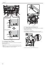
5.3.2.10 Adjusting Delivery of Staple Stack (lower
delivery)
0021-1717
Execute this adjustment in the case of paper displacement (the 1st up to the
3rd cover sheet) in staple stack delivery mode or replacing EEPROM on the
finisher controller PCB.
Adjusting method is as follows:
1) Turn ON the power of the finisher.
2) Turn ON the power switch of the host machine to be on standby.
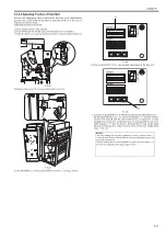
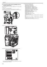
3) Open the front cover and put the door switch tool into the door switch [1].
F-5-75
4) Remove the screw [2] to remove the switch cover [1].
F-5-76
5) Set DIP SW382 [1] on the switch PCB as shown in the figure below.
F-5-77
6) Pressing switch SW385 [1] activates the LED [2] with "0" blinking. The
Adjustment is ready now.
F-5-78
7) Set 3 sheets of A3-size originals on the ADF. Specify 1 set of A4 size (sta-
ple-sort) on the control panel.
8) Execute copy with the start key on the control panel.
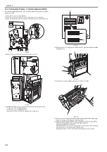
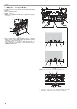
9) Open the upper cover and measure displacement amount of the paper
stack that is stopped at the buffer assembly (displacement amount be-
tween the 1st sheet and the 2nd sheet: A, displacement amount between
the 1nd sheet and the 3rd sheet: B).
Repeat this work 5 times and check that the average of A and B is within
the specified value (A: 2.5mm +/- 0.5, B: 5.0mm +/- 0.5). If the result is
out of the specified value, execute the work as follows.
CAUTION:
If the LED indicates anything other than "0" meaning the adjustment failure,
execute the adjustment again.
[1]
[1]
[2]
[1]
SW382
SW381
SW383
(-)
(+)
ENTER
SW384 SW385
DSP381
SW382
SW381
SW383
(-)
(+)
ENTER
SW384 SW385
DSP381
[2]
[1]
Summary of Contents for Saddle Finisher-AF2
Page 1: ...SERVICE MANUAL Saddle Finisher AF2 MARCH 6 2009...
Page 2: ......
Page 6: ......
Page 12: ...Contents...
Page 13: ...Chapter 1 Specifications...
Page 14: ......
Page 16: ......
Page 22: ......
Page 23: ...Chapter 2 Installation...
Page 24: ......
Page 26: ......
Page 55: ...Chapter 3 Functions...
Page 56: ......
Page 58: ......
Page 104: ...Chapter 3 3 46...
Page 105: ...Chapter 4 Parts Replacement Procedure...
Page 106: ......
Page 110: ......
Page 157: ...Chapter 4 4 47 F 4 213 3 2 1...
Page 158: ......
Page 159: ...Chapter 5 Maintenance...
Page 160: ......
Page 209: ...Chapter 5 5 47 F 5 221 SW382 SW381 SW383 ENTER SW384 SW385 DSP381 1...
Page 218: ......
Page 219: ...Appendix...
Page 220: ......
Page 221: ...General Timing Chart General Circuit Diagram Finisher Sorter DeliveryTray Saddle Finisher AF2...
Page 222: ......
Page 224: ......
Page 225: ...Contents 1 General Circuit Diagram 1 Signal Names 1 General Circuit Diagram 9...
Page 226: ......
Page 243: ......
Page 244: ......


