Chapter 5
5-22
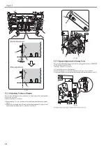
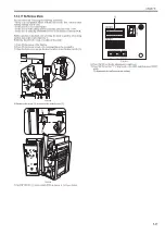
amount for the specified value.
Pressing SW383 [1] moves the staple position upward while pressing
SW384 [2] moves the staple position downward.
Adjustment range: +10 to -10 (correction amount per unit: 0.125mm)
After the adjustment value is specified, go through the following
procedure.
- No paper -> the adjustment value is overwritten and the mode
terminates.
- Paper present -> re-check the staple position and go back to step 8).
F-5-99
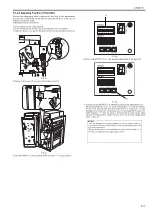
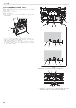
5.3.2.13 Adjusting Saddle Folding Position
0021-1720
Execute this adjustment in the case of displacement in folding position (sad-
dle delivery) or replacing EEPROM on the finisher controller PCB.
Adjusting method is as follows:
1) Turn ON the power of the finisher.
2) Turn ON the power switch of the host machine to be on standby.
3) Specify the booklet with 2 sheets or more (any) on the control panel and
make a copy.
4) Spread the bound paper to measure the folding position [2] against the sta-
ple position [1].
Adjustment is complete if the measured value is within the specification
(C = 0.5mm or less), otherwise execute the following work.
F-5-100
5) Open the front door and put the door switch tool into the door switch [1].
F-5-101
6) Remove the screw [2] to remove the switch cover [1].
F-5-102
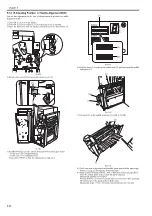
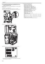
7) Set DIP SW382 [1] on the switch PCB as shown in the figure below.
Then, press SW385 once so that the adjustment is ready now.
F-5-103
8) Work with the 2 push switches (SW383, 384) by calculating correction
value from the measured value.
Pressing SW383 [1] moves the folding position [2] upward while
pressing SW384 [2] moves the folding position [2] downward.
Adjustment range: +16 to -16 (correction amount per unit: 0.125mm)
SW382
SW381
SW383
(-)
(+)
ENTER
SW384 SW385
DSP381
[1]
[2]
[1]
[2]
[C]
[1]
[2]
[1]
SW382
SW381
SW383
(-)
(+)
ENTER
SW384 SW385
DSP381
[1]
Summary of Contents for Saddle Finisher-AF2
Page 1: ...SERVICE MANUAL Saddle Finisher AF2 MARCH 6 2009...
Page 2: ......
Page 6: ......
Page 12: ...Contents...
Page 13: ...Chapter 1 Specifications...
Page 14: ......
Page 16: ......
Page 22: ......
Page 23: ...Chapter 2 Installation...
Page 24: ......
Page 26: ......
Page 55: ...Chapter 3 Functions...
Page 56: ......
Page 58: ......
Page 104: ...Chapter 3 3 46...
Page 105: ...Chapter 4 Parts Replacement Procedure...
Page 106: ......
Page 110: ......
Page 157: ...Chapter 4 4 47 F 4 213 3 2 1...
Page 158: ......
Page 159: ...Chapter 5 Maintenance...
Page 160: ......
Page 209: ...Chapter 5 5 47 F 5 221 SW382 SW381 SW383 ENTER SW384 SW385 DSP381 1...
Page 218: ......
Page 219: ...Appendix...
Page 220: ......
Page 221: ...General Timing Chart General Circuit Diagram Finisher Sorter DeliveryTray Saddle Finisher AF2...
Page 222: ......
Page 224: ......
Page 225: ...Contents 1 General Circuit Diagram 1 Signal Names 1 General Circuit Diagram 9...
Page 226: ......
Page 243: ......
Page 244: ......

