Chapter 2
2-13
F-2-41
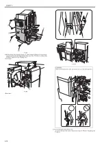
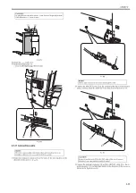
8) Install the rear small cover.
9) Install the shunt cable [1].
- 2 screws (RS tightening; M4X10) [2]
F-2-42
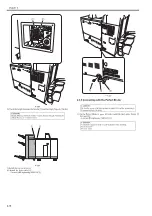
2.3.7 Connecting with the Paper Folding Unit
0020-9250
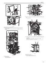
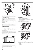
1) On the Paper Folding Unit's upper left side, install the latch plate (front)
[1] (for rear) [2].
- 4 screws (RS tightening; M4X10) [3]
F-2-43
2) Fit the positioning pin [1].
- 2 screws (RS tightening; M4X10) [2]
F-2-44
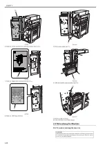
3) Remove the rear cover [1].
- 8 screws [2]
CAUTION:
Height difference should be /-2mm. Execute "Height Adjustment"
if the difference is +/- 2mm or more.
CAUTION:
Be sure the power of the host machine is turned OFF and the power plug is
disconnected from the outlet.
CAUTION:
Confirm the engraved mark on each latch plate when attaching.
For front [1]: F
For rear [2]: R
[1]
[2]
[1]
[2]
[2]
[1]
R
F
[2]
[3]
[1]
[3]
[2]
[1]
[1]
[2]
Summary of Contents for Saddle Finisher-AF2
Page 1: ...SERVICE MANUAL Saddle Finisher AF2 MARCH 6 2009...
Page 2: ......
Page 6: ......
Page 12: ...Contents...
Page 13: ...Chapter 1 Specifications...
Page 14: ......
Page 16: ......
Page 22: ......
Page 23: ...Chapter 2 Installation...
Page 24: ......
Page 26: ......
Page 55: ...Chapter 3 Functions...
Page 56: ......
Page 58: ......
Page 104: ...Chapter 3 3 46...
Page 105: ...Chapter 4 Parts Replacement Procedure...
Page 106: ......
Page 110: ......
Page 157: ...Chapter 4 4 47 F 4 213 3 2 1...
Page 158: ......
Page 159: ...Chapter 5 Maintenance...
Page 160: ......
Page 209: ...Chapter 5 5 47 F 5 221 SW382 SW381 SW383 ENTER SW384 SW385 DSP381 1...
Page 218: ......
Page 219: ...Appendix...
Page 220: ......
Page 221: ...General Timing Chart General Circuit Diagram Finisher Sorter DeliveryTray Saddle Finisher AF2...
Page 222: ......
Page 224: ......
Page 225: ...Contents 1 General Circuit Diagram 1 Signal Names 1 General Circuit Diagram 9...
Page 226: ......
Page 243: ......
Page 244: ......

