Chapter 4
4-10
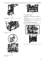
3) Lift the upper cover [1] as the direction of the arrow, and remove the in-
side cover (upper) [2].
- 4 screws [3]
F-4-37
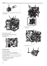
4.2.9 Inside Cover (Lower)
4.2.9.1 Removing the Inside Cover (Lower)
0020-8354
1) Open the front cover.
2) Remove the inside cover (lower).
- 2 screws [2]
F-4-38
4.3 Drive System
4.3.1 Buffer Pass Motor
4.3.1.1 Preparation for Removing Buffer Motor
0020-8849
Remove the rear upper cover (right).
Reference[Removing the
Rear Upper Cover (Right)]
2) Remove the rear upper cover (left).
Reference[Removing the
Rear Upper Cover (Left)]
Remove the rear cover.
Reference[Removing the Rear Cover]
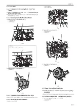
4.3.1.2 Removing the Buffer Motor
0020-8850
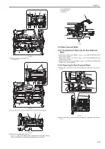
1) Remove the cable guide [1].
- 1 brake cable [2]
- 7 connectors [3]
- 2 screws [4]
F-4-39
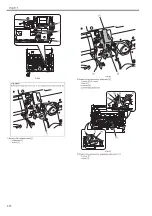
2) Remove the buffer motor unit [1].
- 1 connector [2]
- 2 screws [3]
F-4-40
3) Remove the buffer motor [1].
- 2 screws [2]
F-4-41
[1]
[2]
[3]
[1]
[1]
[2]
[1]
[1]
[1]
[1]
[1]
[2]
[3]
[3]
[1]
[2]
[2]
Summary of Contents for Saddle Finisher-AF2
Page 1: ...SERVICE MANUAL Saddle Finisher AF2 MARCH 6 2009...
Page 2: ......
Page 6: ......
Page 12: ...Contents...
Page 13: ...Chapter 1 Specifications...
Page 14: ......
Page 16: ......
Page 22: ......
Page 23: ...Chapter 2 Installation...
Page 24: ......
Page 26: ......
Page 55: ...Chapter 3 Functions...
Page 56: ......
Page 58: ......
Page 104: ...Chapter 3 3 46...
Page 105: ...Chapter 4 Parts Replacement Procedure...
Page 106: ......
Page 110: ......
Page 157: ...Chapter 4 4 47 F 4 213 3 2 1...
Page 158: ......
Page 159: ...Chapter 5 Maintenance...
Page 160: ......
Page 209: ...Chapter 5 5 47 F 5 221 SW382 SW381 SW383 ENTER SW384 SW385 DSP381 1...
Page 218: ......
Page 219: ...Appendix...
Page 220: ......
Page 221: ...General Timing Chart General Circuit Diagram Finisher Sorter DeliveryTray Saddle Finisher AF2...
Page 222: ......
Page 224: ......
Page 225: ...Contents 1 General Circuit Diagram 1 Signal Names 1 General Circuit Diagram 9...
Page 226: ......
Page 243: ......
Page 244: ......


