Chapter 5
5-4
F-5-10
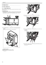
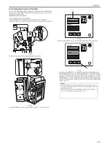
3) Remove the switch cover [1] of the inner cover (lower).
- 1 screw [2]
F-5-11
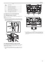
4) Set DIP switch SW382 [1] on the switch PCB as shown in the figure (1,
4, 6, 8: ON), and press ENTER (SW385) button [2], resulting in "0"
blinks on the LED [3].
F-5-12
5) Place a sheet of A4 or LTR paper and set in ADF or the copyboard mode.
And set "3" for copy count to execute printing.
6) The LED [1] displays the adjustment value for side registration/skew.
Check each value. The display shows values in the order of "A" -> "side
registration adjustment value" -> "B" -> "skew adjustment value".
- Side registration adjustment range (estimated value); -3 to +3 mm (1
scale is equivalent to 1mm).
- Skew adjustment range (estimated value); -2 to +2 mm (1 scale is
equivalent to 1mm).
F-5-13
7) Press ENTER button to complete the adjustment mode.
If the adjustment value (estimated value) is within the range, set the DIP
switch back and complete the adjustment.
If the adjustment value (estimated value) is out of the range, execute "2.
Side registration adjustment" or "3. Skew adjustment".
8) Turn ON the power switch of the host machine then the finisher.
2. Side registration adjustment
1) Separate the finisher from the host machine.
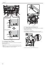
2) Loosen the 2 screws [2] on the positioning plate [1] at the right side.
3) If the value obtained at "checking adjustment value" is "+ (positive)",
move it in [A] direction and tighten the screws [2].
If the value obtained at "checking adjustment value" is "- (negative)",
move it in [B] direction and tighten the screws [2].
F-5-14
3. Skew adjustment
If the skew adjustment value is within the range, start from step 7).
1) Push and hold the claw [1] in [A] direction and remove the 3 knobs [2]
toward [B] direction.
[1]
[2]
[1]
SW382
SW381
SW383
(-)
(+)
ENTER
SW384 SW385
DSP381
[3]
[1]
[2]
SW382
SW381
SW383
(-)
(+)
ENTER
SW384 SW385
DSP381
[1]
[1]
[2]
[A]
[B]
Summary of Contents for Saddle Finisher-AF2
Page 1: ...SERVICE MANUAL Saddle Finisher AF2 MARCH 6 2009...
Page 2: ......
Page 6: ......
Page 12: ...Contents...
Page 13: ...Chapter 1 Specifications...
Page 14: ......
Page 16: ......
Page 22: ......
Page 23: ...Chapter 2 Installation...
Page 24: ......
Page 26: ......
Page 55: ...Chapter 3 Functions...
Page 56: ......
Page 58: ......
Page 104: ...Chapter 3 3 46...
Page 105: ...Chapter 4 Parts Replacement Procedure...
Page 106: ......
Page 110: ......
Page 157: ...Chapter 4 4 47 F 4 213 3 2 1...
Page 158: ......
Page 159: ...Chapter 5 Maintenance...
Page 160: ......
Page 209: ...Chapter 5 5 47 F 5 221 SW382 SW381 SW383 ENTER SW384 SW385 DSP381 1...
Page 218: ......
Page 219: ...Appendix...
Page 220: ......
Page 221: ...General Timing Chart General Circuit Diagram Finisher Sorter DeliveryTray Saddle Finisher AF2...
Page 222: ......
Page 224: ......
Page 225: ...Contents 1 General Circuit Diagram 1 Signal Names 1 General Circuit Diagram 9...
Page 226: ......
Page 243: ......
Page 244: ......


