Chapter 2
2-22
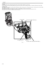
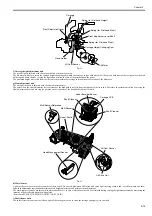
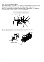
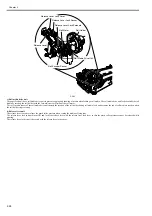
b) Wiper unit
The wiper unit operated by the purge motor wipes the printhead face.
The printer is provided with a pair of wiper blades for better wiping performance.
The wiping operation is performed by a "slide wipe" method by which the purge motor rotates (in the normal direction) to slide the wiper blade via the wiper cam.
It is performed by a constant-speed movement toward the front of the printer as viewed from the printer front.
The wiper blade, which is positioned at right angles to the printhead, wipes the entire printhead face, and then the narrow blade is used to wipe the nozzle arrays.
After wiping, the wipe blades are cleaned before they are set at the wiping position so that the maximum wiping performance is obtained.
During the wiper blade cleaning, the ink removed form the head is rubbed off by the in scraper.
Absorbent material soaked with glycerin is pressed against the wiper blades to enhance the wiping performance. The amount of glycerin used (tank capacity: 50
ml) is managed by counting the number of times the wiper blade is pressed against the absorbent material. When the count reaches the following value, an advance
notice of replacement (printing can be continued) or a request for replacement (service call error) is displayed.
F-2-18
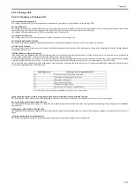
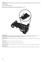
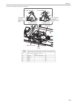
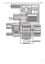
c) Pump unit
This printer uses tube pumps (suction pumps) that press on the ink tubes using rollers to produce negative pressure, thus sucking ink.
Two rollers are used to press on a single tube one after another to control the amount of ink sucked.
The roller rotation timing is detected by the pump cam sensor, and the amount of rotation is controlled by the driving of the purge motor.
F-2-19
Advance notice of replacement
47,500times
Service call
50,000times
Glycerin Tank
Wiper Blade
Wiper Cam
Cap
Blade Holder
Glycerin Absorbent Material
Ink Scraper
Printhead
Purge Motor
Push Rollers
To Maintenance Cartridge
Pump Encoder Sensor
Pump Cam Sensor
Cap
Pump Unit
Cap
Ink Tubes
Suction Pump
Summary of Contents for image Prograf iPF780 Series
Page 1: ...Mar 27 2014 Service Manual iPF780 760 750 series iPF785...
Page 9: ...Chapter 1 PRODUCT DESCRIPTION...
Page 57: ...Chapter 2 TECHNICAL REFERENCE...
Page 117: ...Chapter 3 INSTALLATION...
Page 125: ...Chapter 4 DISASSEMBLY REASSEMBLY...
Page 175: ...Chapter 4 4 49 2 Shaft Cleaner 1 F 4 97 1 1...
Page 176: ...Chapter 4 4 50 3 Upper Cover Hinge Catch 1 Roll Cover Slide Guide 2 F 4 98 2 1...
Page 179: ...Chapter 5 MAINTENANCE...
Page 186: ...Chapter 6 TROUBLESHOOTING...
Page 212: ...Chapter 7 SERVICE MODE...
Page 267: ...Mar 19 2014 PARTS CATALOG iPF786 785 781 780 765 760 755 750...
Page 301: ...2 25 FIGURE 10 PLATEN GUIDE UNIT 1 3 6 2 8 4 5 10 10 10 9 9 11...
Page 326: ......

