Chapter 2
2-47
2.4.5 Power Supply
2.4.5.1 Power supply block diagram
0013-4333
F-2-35
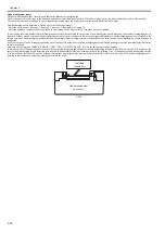
The power supply converts AC voltages ranging from 100 V to 240 V from the AC inlet to DC voltages for driving the ICs, motor, and others.
The voltage generator circuits include the +26 V generation circuit for driving motors, fans, and sensors and a +21.5 V generator circuit for driving sensors, heads,
logic circuits, and others.
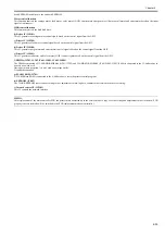
When the power is turned off, +26 V and +21.5 V are reduced to about 12 V and 9 V respectively (power save mode).
Power ON/OFF operation is controlled by the main controller PCB.
Operation panel
Transformer
DC power supply
control circuit
+21.5V
generation circuit
+26V
generation circuit
POWER ON
Rectifying circuit
Noize filter circuit
AC inlet
100V to 240V
Power supply
Main controller PCB
+5V/+3.3V
generation circuit
Summary of Contents for image Prograf iPF780 Series
Page 1: ...Mar 27 2014 Service Manual iPF780 760 750 series iPF785...
Page 9: ...Chapter 1 PRODUCT DESCRIPTION...
Page 57: ...Chapter 2 TECHNICAL REFERENCE...
Page 117: ...Chapter 3 INSTALLATION...
Page 125: ...Chapter 4 DISASSEMBLY REASSEMBLY...
Page 175: ...Chapter 4 4 49 2 Shaft Cleaner 1 F 4 97 1 1...
Page 176: ...Chapter 4 4 50 3 Upper Cover Hinge Catch 1 Roll Cover Slide Guide 2 F 4 98 2 1...
Page 179: ...Chapter 5 MAINTENANCE...
Page 186: ...Chapter 6 TROUBLESHOOTING...
Page 212: ...Chapter 7 SERVICE MODE...
Page 267: ...Mar 19 2014 PARTS CATALOG iPF786 785 781 780 765 760 755 750...
Page 301: ...2 25 FIGURE 10 PLATEN GUIDE UNIT 1 3 6 2 8 4 5 10 10 10 9 9 11...
Page 326: ......

