Chapter 1
1-41
1.7.1.3 Electric Parts
0023-1464
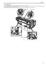
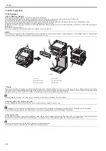
The electric parts of the printer are activated when the printer is connected to the AC power supply.
At the rear and left/right side of the printer are the main controller, power supply, HDD, and interface connector. The carriage PCB is incorporated in the carriage
unit, and the operation panel is on the upper right top cover.
When serving the printer with the cover removed, be extremely careful to avoid electric shock and shorting electrical devices.
F-1-35
Carriage PCB
Operation Panel
Power Supply PCB
AC Inlet
Hard Disk Drive
Main Controller PCB
Interface Connector
Summary of Contents for image Prograf iPF780 Series
Page 1: ...Mar 27 2014 Service Manual iPF780 760 750 series iPF785...
Page 9: ...Chapter 1 PRODUCT DESCRIPTION...
Page 57: ...Chapter 2 TECHNICAL REFERENCE...
Page 117: ...Chapter 3 INSTALLATION...
Page 125: ...Chapter 4 DISASSEMBLY REASSEMBLY...
Page 175: ...Chapter 4 4 49 2 Shaft Cleaner 1 F 4 97 1 1...
Page 176: ...Chapter 4 4 50 3 Upper Cover Hinge Catch 1 Roll Cover Slide Guide 2 F 4 98 2 1...
Page 179: ...Chapter 5 MAINTENANCE...
Page 186: ...Chapter 6 TROUBLESHOOTING...
Page 212: ...Chapter 7 SERVICE MODE...
Page 267: ...Mar 19 2014 PARTS CATALOG iPF786 785 781 780 765 760 755 750...
Page 301: ...2 25 FIGURE 10 PLATEN GUIDE UNIT 1 3 6 2 8 4 5 10 10 10 9 9 11...
Page 326: ......


