


Chapter 14
14-18
mounted, be sure to turn the power on in the order of the delivery accessory
to the host machine. If you turn on the power in reverse order, the delivery
accessory cannot be correctly recognized.
1) Turn the power on.
2) Execute the followings in service mode.
- COPIER > FUNCTION > CLEAR > DC-CON (Clear the RAM of the DC
controller PCB)
- COPIER > FUNCTION > CLEAR > CNT-DCON (Clear the service coun-
ter of the DC controller PCB)
3) Turn the power off and back to on. (Turning the power off/on executes to
clear the RAM.)
4) Input the order of connecting the delivery accessories in service mode be-
low.
- COPIER > OPTION > ACCPSD-D > ACC1 through ACC8 (Set the order
of connecting the delivery accessories.)
5) Turn the power off and back to on. (Turning the power off/on enables the
setting of the connection order of the delivery accessories and the deliv-
ery accessories can be recognized.)
6) Input "0" in the service mode below.
- COPIER > OPTION > BODY > FIX-EXP (Fixing exp control mode)
7) Input the value on the service label in the appropriate item of service
mode.
8) Turn the power off and back to on. (Turning the power off/on enables the
value input in service mode.)
9) Execute the followings in service mode.
- COPIER > FUNCTION > MISC-P > CL-ADJ (Level 2)
- COPEIR > FUNCTION > SENS-ADJ > OP-SENS (Level2)
10) Input the value on the label of new DC controller PCB in the appropriate
item of service mode.
F-14-34
[1] COPIER > ADJUST > DEVELOP > D-HV-DE
[2] COPIER > ADJUST > HV-TR > D-HV-TR
[3] COPIER > ADJUST > HV-TR > D-PRE-TR
[4] COPIER > ADJUST > HV-SP > D-HV-SP
[5] COPIER > ADJUST > DEVELOP > OFFSETDA
11) Turn the power off and back to on.
14.7.4 After Replacing the Reader Controller PCB
0011-8214
iR7105 / iR7095
Before Starting the Work (backing up the data)
If possible, perform the following:
- Using the SST, download the data stored in the RAM of the reader control-
ler PCB.
- Print out the user mode/service mode data.
1) Turn on the power, and execute the following service mode item:
COPIER > FUNCTION > CLEAR > R-CON
2) If the data has successfully been downloaded using the SST before the re-
placement, upload the data.
3) Set the values indicated on the service label for their respective service
mode items.
COPIER > ADJUST > ADJ-XY > ADJ-X (adjustment of image read start
position in sub scanning direction; image lead edge)
COPIER > ADJUST > ADJ-XY > ADJ-Y (adjustment of image read start
position in main scanning direction; horizontal registration)
COPIER > ADJUST > ADJ-XY > ADJ-S (adjustment of shading correction
data measurement position)
COPIER > ADJUST > ADJ-XY > ADJ-Y-DF (adjustment of main scanning
position for ADF stream reading)
COPIER > ADJUST > ADJ-XY > ADJ-Y-FX (adjustment of main scanning
position for ADF fixed reading)
COPIER > ADJUST > ADJ-XY > ADJ-X-MG (fine-adjustment of magnifi-
cation in sub scanning direction for copyboard reading)
4) Execute the following service mode item:
COPIER> FUNCTION> CCD> CCD-ADJ (shading correction based on
standard white plate)
5) Turn off and then on the power.
14.7.5 After Replacing the Reader Controller PCB
0011-8729
iR7086
Before Starting the Work (backing up the data)
If possible, perform the following:
- Using the SST, download the data stored in the RAM of the reader control-
ler PCB.
- Print out the user mode/service mode data.
1) Turn on the power, and execute the following service mode item:
COPIER > FUNCTION > CLEAR > R-CON
2) If the data has successfully been downloaded using the SST before the re-
placement, upload the data.
3) Set the values indicated on the service label for their respective service
mode items.
COPIER > ADJUST > ADJ-XY > ADJ-X (adjustment of image read start
position in sub scanning direction; image lead edge)
COPIER > ADJUST > ADJ-XY > ADJ-Y (adjustment of image read start
position in main scanning direction; horizontal registration)
COPIER > ADJUST > ADJ-XY > ADJ-S (adjustment of shading correction
data measurement position)
COPIER > ADJUST > ADJ-XY > ADJ-Y-DF (adjustment of main scanning
position for ADF stream reading)
COPIER > ADJUST > ADJ-XY > STRD-POS (adjustment of CCD read po-
sition for ADF stream reading)
COPIER > ADJUST > ADJ-XY > ADJ-X-MG (fine-adjustment of magnifi-
cation in sub scanning direction for copyboard reading)
FEEDER > ADJUST > DOCST (adjustment of original stop position for
ADF pickup)
FEEDER > ADJUST > LA-SPEED (adjustment of original transport speed
for ADF stream reading)
4) Execute the following service mode items:
COPIER> FUNCTION> CCD> CCD-ADJ (shading correction based on
standard white plate)
COPIER> FUNCTION> CCD> DF-WLVL1 (ADF white level adjustment;
for copyboard reading)
COPIER> FUNCTION> CCD> DF-WLVL2 (ADF white level adjustment;
for stream reading)
5) Turn off and then on the power.
MEMO:
In the case of the model with the DADF-M1 (outside Japan: iR7086), the
ADF-related service mode data is stored in the RAM of the reader controller.
As such, if you have initialized the RAM on the reader controller PCB or re-
placed the PCB, it is important that you newly enter service mode settings
and execute appropriate adjustment items.
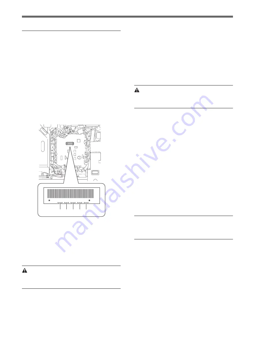
14.7.6 After Replacing the HV-DC PCB
0010-9330
iR7105 / iR7095 / iR7086
1) Set the values (5 types) indicated on the label attached to the new HV-DC
PCB for the respective service mode items:
DC+09+28+24+09+25
[1] [2] [3] [4] [5]
Summary of Contents for 7086 Series
Page 1: ...Sep 7 2007 Service Manual iR7105 7095 7086 Series ...
Page 2: ......
Page 6: ......
Page 26: ...Contents ...
Page 27: ...Chapter 1 Introduction ...
Page 28: ......
Page 30: ......
Page 32: ...Chapter 1 1 2 Not all products are necessarily available in all sales areas ...
Page 55: ...Chapter 2 Installation ...
Page 56: ......
Page 150: ......
Page 151: ...Chapter 3 Basic Operation ...
Page 152: ......
Page 154: ......
Page 159: ...Chapter 4 Main Controller ...
Page 160: ......
Page 162: ......
Page 183: ...Chapter 5 Original Exposure System ...
Page 184: ......
Page 228: ......
Page 229: ...Chapter 6 Laser Exposure ...
Page 230: ......
Page 232: ......
Page 238: ...Chapter 6 6 6 F 6 7 1 Laser light 2 Laser shutter 1 2 1 2 2 1 ...
Page 240: ......
Page 241: ...Chapter 7 Image Formation ...
Page 242: ......
Page 246: ......
Page 294: ......
Page 295: ...Chapter 8 Pickup Feeding System ...
Page 296: ......
Page 300: ......
Page 353: ...Chapter 9 Fixing System ...
Page 354: ......
Page 378: ......
Page 379: ...Chapter 10 External and Controls ...
Page 380: ......
Page 384: ......
Page 394: ...Chapter 10 10 10 F 10 7 ...
Page 417: ...Chapter 11 MEAP ...
Page 418: ......
Page 420: ......
Page 466: ......
Page 467: ...Chapter 12 RDS ...
Page 468: ......
Page 470: ......
Page 479: ...Chapter 13 Maintenance and Inspection ...
Page 480: ......
Page 482: ......
Page 496: ......
Page 497: ...Chapter 14 Standards and Adjustments ...
Page 498: ......
Page 526: ......
Page 527: ...Chapter 15 Correcting Faulty Images ...
Page 528: ......
Page 530: ......
Page 560: ......
Page 561: ...Chapter 16 Self Diagnosis ...
Page 562: ......
Page 564: ......
Page 584: ......
Page 585: ...Chapter 17 Service Mode ...
Page 586: ......
Page 588: ...Contents 17 8 1 1 COPIER Items 17 94 ...
Page 688: ......
Page 689: ...Chapter 18 Upgrading ...
Page 690: ......
Page 692: ......
Page 696: ...Chapter 18 18 4 ...
Page 713: ...Chapter 18 18 22 formatting and download the system software once again ...
Page 726: ...Chapter 19 Service Tools ...
Page 727: ......
Page 729: ......
Page 733: ......
Page 734: ...Sep 7 2007 ...
Page 735: ......


