


Chapter 10
10-21
10.5.17 Drum Heater Switch Assembly
10.5.17.1 Removing the Drum Heater Switch Assembly
0010-9614
iR7105 / iR7095 / iR7086
1) Remove the rear cover.
2) Remove the left lower cover. (4 screws)
3) Remove the 3 screws [1], and disconnect the 7 connectors [2]; then, de-
tached power cord base [3]. thereafter, free the fixing claw to detach the
drum heat switch [4].
F-10-71
10.5.18 DC Controller PCB
10.5.18.1 Removing the DC Controller PCB
0010-9613
iR7105 / iR7095 / iR7086
1) Remove the rear cover.
2) Disconnect all connectors of the PCB, and remove the 4 screws [1];
then, detach the DC controller PCB [2].
F-10-72
10.5.18.2 After Replacing the DC Controller PCB
0010-9611
iR7105 / iR7095 / iR7086
Before starting the work and checking
- Be sure to print out the user mode/service mode data before replacing the
DC controller PCB.
- Be sure to adjust the on/off timing of the clutch in service mode (COPIER
> FUNCTION > MISC-P > CL-ADJ) after replacing the DC controller
PCB. Before adjusting, be sure to place two or more sheets of A4 or LTR
in the following pick-up slots, otherwise you can't perform the adjust-
ment.
- Left deck
- Cassette 4
- Paper deck (accessory)
Points to note when turning the power off (Executing the shutdown
sequence)
Be sure to turn off the main power after executing the shutdown sequence to
protect the hard disk.
Points to note when turning the power on (When Delivery accessory
is mounted)
When any delivery accessory (Finisher, Stacker, and/or Perfect binder) is
mounted, be sure to turn the power on in the order of the delivery accessory
to the host machine. If you turn on the power in reverse order, the delivery
accessory cannot be correctly recognized.
1) Turn the power on.
2) Execute the followings in service mode.
- COPIER > FUNCTION > CLEAR > DC-CON (Clear the RAM of the DC
controller PCB)
- COPIER > FUNCTION > CLEAR > CNT-DCON (Clear the service coun-
ter of the DC controller PCB)
3) Turn the power off and back to on. (Turning the power off/on executes to
clear the RAM.)
4) Input the order of connecting the delivery accessories in service mode be-
low.
- COPIER > OPTION > ACCPSD-D > ACC1 through ACC8 (Set the order
of connecting the delivery accessories.)
5) Turn the power off and back to on. (Turning the power off/on enables the
setting of the connection order of the delivery accessories and the deliv-
ery accessories can be recognized.)
6) Input "0" in the service mode below.
- COPIER > OPTION > BODY > FIX-EXP (Fixing exp control mode)
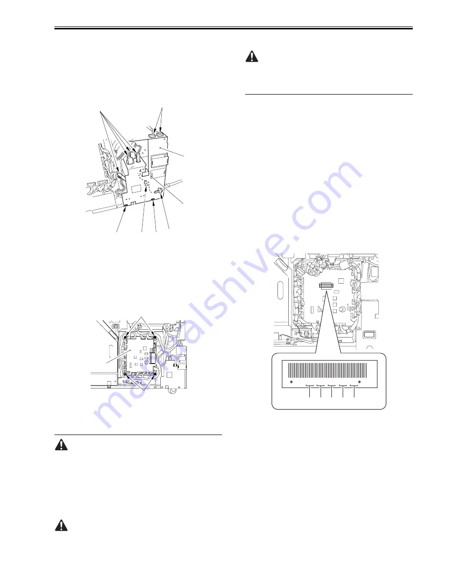
7) Input the value on the service label in the appropriate item of service
mode.
8) Turn the power off and back to on. (Turning the power off/on enables the
value input in service mode.)
9) Execute the followings in service mode.
- COPIER > FUNCTION > MISC-P > CL-ADJ (Level 2)
- COPEIR > FUNCTION > SENS-ADJ > OP-SENS (Level2)
10) Input the value on the label of new DC controller PCB in the appropriate
item of service mode.
F-10-73
[1] COPIER > ADJUST > DEVELOP > D-HV-DE
[2] COPIER > ADJUST > HV-TR > D-HV-TR
[3] COPIER > ADJUST > HV-TR > D-PRE-TR
[4] COPIER > ADJUST > HV-SP > D-HV-SP
[5] COPIER > ADJUST > DEVELOP > OFFSETDA
11) Turn the power off and back to on.
10.5.19 Control Panel Inverter PCB
10.5.19.1 Before Starting the Work
0011-8154
iR7105 / iR7095 / iR7086
1) Remove the control panel.
2) Remove the 5 rubber pieces [1] from the back of the control panel.
[2]
[2]
[2]
[1]
[1]
[1]
[3]
[4]
[1]
[1]
[2]
DC+09+28+24+09+25
[1] [2] [3] [4] [5]
Summary of Contents for 7086 Series
Page 1: ...Sep 7 2007 Service Manual iR7105 7095 7086 Series ...
Page 2: ......
Page 6: ......
Page 26: ...Contents ...
Page 27: ...Chapter 1 Introduction ...
Page 28: ......
Page 30: ......
Page 32: ...Chapter 1 1 2 Not all products are necessarily available in all sales areas ...
Page 55: ...Chapter 2 Installation ...
Page 56: ......
Page 150: ......
Page 151: ...Chapter 3 Basic Operation ...
Page 152: ......
Page 154: ......
Page 159: ...Chapter 4 Main Controller ...
Page 160: ......
Page 162: ......
Page 183: ...Chapter 5 Original Exposure System ...
Page 184: ......
Page 228: ......
Page 229: ...Chapter 6 Laser Exposure ...
Page 230: ......
Page 232: ......
Page 238: ...Chapter 6 6 6 F 6 7 1 Laser light 2 Laser shutter 1 2 1 2 2 1 ...
Page 240: ......
Page 241: ...Chapter 7 Image Formation ...
Page 242: ......
Page 246: ......
Page 294: ......
Page 295: ...Chapter 8 Pickup Feeding System ...
Page 296: ......
Page 300: ......
Page 353: ...Chapter 9 Fixing System ...
Page 354: ......
Page 378: ......
Page 379: ...Chapter 10 External and Controls ...
Page 380: ......
Page 384: ......
Page 394: ...Chapter 10 10 10 F 10 7 ...
Page 417: ...Chapter 11 MEAP ...
Page 418: ......
Page 420: ......
Page 466: ......
Page 467: ...Chapter 12 RDS ...
Page 468: ......
Page 470: ......
Page 479: ...Chapter 13 Maintenance and Inspection ...
Page 480: ......
Page 482: ......
Page 496: ......
Page 497: ...Chapter 14 Standards and Adjustments ...
Page 498: ......
Page 526: ......
Page 527: ...Chapter 15 Correcting Faulty Images ...
Page 528: ......
Page 530: ......
Page 560: ......
Page 561: ...Chapter 16 Self Diagnosis ...
Page 562: ......
Page 564: ......
Page 584: ......
Page 585: ...Chapter 17 Service Mode ...
Page 586: ......
Page 588: ...Contents 17 8 1 1 COPIER Items 17 94 ...
Page 688: ......
Page 689: ...Chapter 18 Upgrading ...
Page 690: ......
Page 692: ......
Page 696: ...Chapter 18 18 4 ...
Page 713: ...Chapter 18 18 22 formatting and download the system software once again ...
Page 726: ...Chapter 19 Service Tools ...
Page 727: ......
Page 729: ......
Page 733: ......
Page 734: ...Sep 7 2007 ...
Page 735: ......


