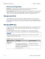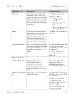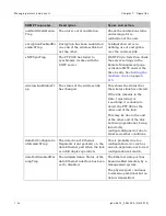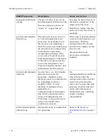
Managing 1+ 1 Hot St andby links
Chapt er 7: Operat ion
7- 34
phn- 2513_004v000 ( Oct 2012)
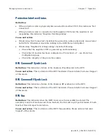
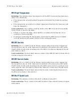
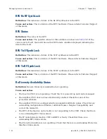
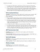
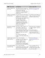
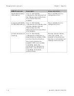
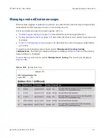
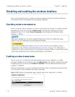
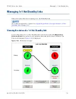
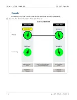
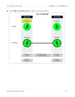
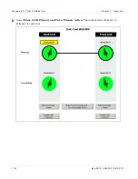
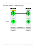
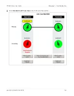
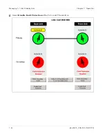
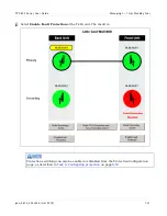
This page shows the same view of the link from the web interface of any of the four units.
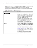
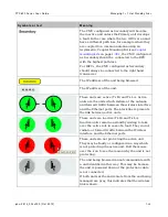
The positions of the units on the page are determined by their Tx Hi/Lo and
Primary/Secondary mode settings. The symbols, text and their meanings are shown in
Ta ble 2 6 0
Prot ect ed Link page sym bols and t ext
Sym bols or t e x t
M e a n in g
Each end of the link is identified by a Site Name.
The Site Name is configured using the Install
Wizard or can be updated using the Configuration
page. At a given end, it is recommended that the
Site Name is configured to the same name for
both Primary and Secondary CMUs.
The end which is configured with the transmit
frequency on the high side of the FDD frequency
plan (Tx Hi) is always shown on the left.
If no Site Name has been configured at either
end, the labels will indicate Tx Hi or Tx Lo.
The CMU configured as Primary is the preferred
unit in that it will become the active unit unless it
is faulty. In the case where the two ODUs at an
end have a different path loss, for example where
they are coupled to a common antenna using an
asymmetric coupler mounting kit (see
) , the CMU configured
as Primary should be connected to the RFU with
the lowest path loss.
For IRFUs, the CMU configured as Primary
should always be connected to the left hand
transceiver.
Summary of Contents for PTP 800 Series
Page 1: ...Cambium PTP 800 Series User Guide System Release 800 05 02 ...
Page 40: ...Licensing requirements About This User Guide 10 phn 2513_004v000 Oct 2012 ...
Page 232: ...Limit of liability Chapter 3 Legal information 3 22 phn 2513_004v000 Oct 2012 ...
Page 322: ...Radiation hazard assessm ent Chapter 4 Reference information 4 90 phn 2513_004v000 Oct 2012 ...
Page 428: ...Replacing IRFU components Chapter 5 Installation 5 106 phn 2513_004v000 Oct 2012 ...
Page 630: ...Using recovery mode Chapter 7 Operation 7 78 phn 2513_004v000 Oct 2012 ...

