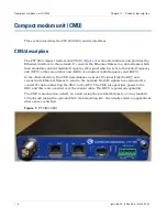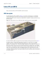
Com pact m odem unit ( CMU)
Chapt er 1: Product descript ion
1- 10
phn- 2513_004v000 ( Oct 2012)
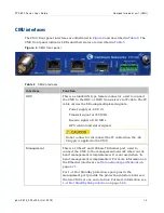
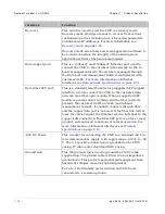
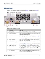
I n t e r fa ce
Fu n ct ion
Recovery
This switch is used to start the CMU in recovery mode.
Recovery mode provides a means to recover from serious
configuration errors including lost or forgotten passwords
and unknown IP addresses. For more information see
Recovery mode also allows new main application software to
be loaded even when the integrity of the existing main
application software has been compromised.
Data (copper port)
This is a 100baseT and 1000baseT Ethernet port, used to
connect the CMU to the customer data network. In the ‘in-
band’ management mode, the system is managed through
the Data port and management traffic is multiplexed with
customer traffic. For more information on Ethernet
interfaces see
Data network specifications on page 4-71
Data (fiber SFP port)
This is a standard small form-factor pluggable (SFP) gigabit
interface, used to connect the CMU to the customer data
network via a fiber-optic module. When a supported SFP
module is present and is working, and the fiber carrier is
present, the customer traffic network (and in-band
management network, if enabled) connects through fiber,
and the copper data port is not used. If the fiber link fails or
loses the carrier signal, the Ethernet service falls back to the
copper LAN connection. The fiber SFP port is a Class 1 laser
product, safe under all conditions of normal operation. For
more information on Ethernet interfaces see
on page
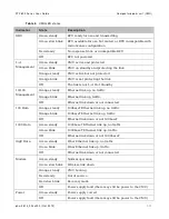
-48V DC Power
This a socket for connecting the CMU to a standard –48 V dc
telecommunications supply, with supply range –40.5 V to –60
V. The 0 V (positive connection) is grounded at the CMU
casing, IF cable outer shield and ODU casing.
Ground stud
This M5 ground stud is used to ground the CMU via the
supplied lug. The ground cable is fitted to a low impedance
ground point. This protects personnel and equipment from
hazardous voltages caused by lightning strikes.
For a 1+1 Hot Standby protected link, both CMUs are
connected to a common ground.
Summary of Contents for PTP 800 Series
Page 1: ...Cambium PTP 800 Series User Guide System Release 800 05 02 ...
Page 40: ...Licensing requirements About This User Guide 10 phn 2513_004v000 Oct 2012 ...
Page 232: ...Limit of liability Chapter 3 Legal information 3 22 phn 2513_004v000 Oct 2012 ...
Page 322: ...Radiation hazard assessm ent Chapter 4 Reference information 4 90 phn 2513_004v000 Oct 2012 ...
Page 428: ...Replacing IRFU components Chapter 5 Installation 5 106 phn 2513_004v000 Oct 2012 ...
Page 630: ...Using recovery mode Chapter 7 Operation 7 78 phn 2513_004v000 Oct 2012 ...

