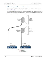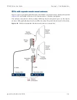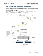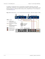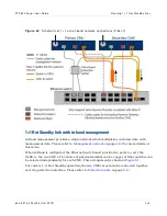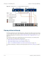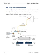
Planning 1+ 1 Hot St andby links
Chapt er 2: Planning considerat ions
2- 48
phn- 2513_004v000 ( Oct 2012)
•
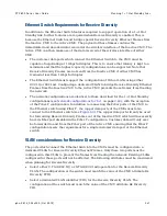
At the Ethernet Switch, configure the Receive Diversity VLAN for tagged operation. At
the ingress, the ports in this VLAN must accept tagged frames which arrive with the
Receive Diversity VID and forward them to the other port which is also a member of
this VLAN. At the egress, the Ethernet Switch must NOT strip the Receive Diversity
tag.
Performance considerations for Receive Diversity
As the Ethernet Switch multiplexes the Receive Diversity Frames with customer traffic,
consider the impact of Receive Diversity on latency and jitter.
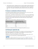
When the link is not fading, the maximum latency increases by 12 µs in all configurations.
When the link fades to the point where the Active unit can no longer demodulate a signal
and where the data stream from the Inactive unit is being used, the maximum latency
increases to a value which is dependent on the frames size of the customer traffic as
shown in
Ta ble 1 2
Fram e size and lat ency relat ionship in Rx SD links
M a x im u m Cu st om e r
Fr a m e Siz e ( oct e t s)
La t e n cy in cr e a se w it h
Re ce ive D iv e r sit y e n a ble d
( µ s)
64
53
1500
64
9600
150
In all cases, the minimum latency does not change hence jitter is increased.
Link Planning for Spatial Diversity
Spatial Diversity can significantly improve the availability of a link, particularly for long
links. Indeed regulations can recommend or even mandate that Spatial Diversity is
deployed for links which are longer than a specific range.
LINKPlanner calculates link availability for all link configurations and provides a very
convenient way of seeing the effect of enabling Spatial Diversity.
When ACM is enabled, Spatial Diversity only increases the availability of the lowest
configured modulation mode. The availability of higher order modes is not increased.
Summary of Contents for PTP 800 Series
Page 1: ...Cambium PTP 800 Series User Guide System Release 800 05 02 ...
Page 40: ...Licensing requirements About This User Guide 10 phn 2513_004v000 Oct 2012 ...
Page 232: ...Limit of liability Chapter 3 Legal information 3 22 phn 2513_004v000 Oct 2012 ...
Page 322: ...Radiation hazard assessm ent Chapter 4 Reference information 4 90 phn 2513_004v000 Oct 2012 ...
Page 428: ...Replacing IRFU components Chapter 5 Installation 5 106 phn 2513_004v000 Oct 2012 ...
Page 630: ...Using recovery mode Chapter 7 Operation 7 78 phn 2513_004v000 Oct 2012 ...

