


2-18
2002 Buell P3: Chassis
HOME
INSTALLATION
1
1
WARNING
1
WARNING
Only install original equipment (stock) tire valves and
valve caps. A valve or valve and cap combination that is
too long may interfere with (strike) adjacent components,
damage the valve and cause rapid tire deflation. Rapid
tire deflation could cause loss of control which could
result in death or serious injury.
1
1
WARNING
1
WARNING
Aftermarket valve caps that are heavier than the stock
cap may have clearance at slow speeds; but, at high
speed the valve/cap will be moved outward by centrifugal
force. This outward movement could cause the valve/cap
to strike the adjacent components, damage the valve and
cause rapid tire deflation. Rapid tire deflation could
cause loss of control which could result in death or seri-
ous injury.
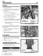
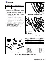
1.
Damaged or leaking valve stems must be replaced.
Place rubber grommet on valve stem with shoulder in
recess of the valve stem head.
2.
Install and tighten nut to 42-44
in-lbs
(4.7-5.0 Nm).
3.
Thoroughly lubricate rim flanges and both beads of tire
with tire lubricant.
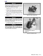
4.
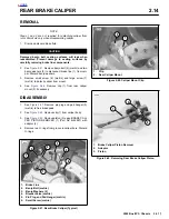
See
Figure 2-22.
Starting at the valve stem, start first
bead into the rim well using a bead breaker machine. If
no machine is available, work bead on as far as possible
by hand. Use a tire tool to pry the remaining bead over
rim flange.
5.
Start 180° from valve stem hole and place second bead
on rim. Work bead onto rim with tire tools, working
toward valve in both directions.
1
1
WARNING
1
WARNING
Do not inflate over 40 psi (276 kPa) to seat the beads.
Inflating the tire beyond 40 psi (276 kPa) to seat the
beads can cause the tire rim assembly to burst with force
which could result in death or serious injury.
6.
Apply air to stem to seat beads on rim. It may be neces-
sary to use a TIRE BEAD EXPANDER (Part No. HD-
28700) on the tire until beads seal on rim.
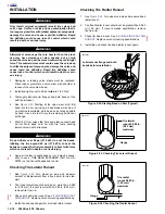
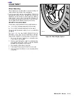
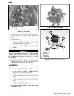
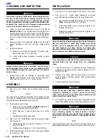
Checking Tire Lateral Runout
1.
See
Figure 2-23.
Turn wheel on axle and measure
amount of displacement from a fixed point to tire side-
wall.
2.
Tire tread lateral runout should be no more than 0.080
in. (2.03 mm). If runout is more than 0.080 in. (2.03 mm),
remove tire from rim.
3.
Check rim bead side runout. See
2.8 CHECKING CAST
RIM RUNOUT
. Replace rims not meeting specifications.
4.
Install tire and check again for tire tread lateral runout.
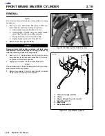
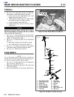
Checking Tire Radial Runout
1.
See
Figure 2-24.
Turn wheel on axle and measure tread
radial runout.
2.
Tire tread radial runout should not be greater than 0.060
in. (1.52 mm). If runout exceeds specification, remove
tire from rim.
3.
Check rim bead runout. See
2.8 CHECKING CAST RIM
RUNOUT
. Replace rims not meeting specifications.
4.
Install tire and check tire tread radial runout again.
Figure 2-22. Starting Bead on Rim (Typical)
Figure 2-23. Checking Tire Lateral Runout
Figure 2-24. Checking Tire Radial Runout
Lubricate rim flange and both
beads before installation
a0209x2x
Tire lateral
runout 0.080 in.
(2.03 mm)
maximum
Gauge
a0210x2x
a0211x2x
Tire radial
runout 0.060 in.
(1.52 mm)
maximum
Gauge
Summary of Contents for 2002 P3
Page 2: ......
Page 17: ...A 15 Appendix A Tools HOME ...
Page 32: ...C 3 Appendix C Metric Conversions HOME ...
Page 41: ...1 8 2002 Buell P3 Maintenance HOME NOTES ...
Page 75: ......
Page 111: ...2 36 2002 Buell P3 Chassis HOME NOTES ...
Page 143: ...2 68 2002 Buell P3 Chassis HOME NOTES ...
Page 144: ...2002 Buell P3 Chassis 2 69 HOME ...
Page 146: ......
Page 147: ......
Page 223: ...3 76 2002 Buell P3 Engine HOME NOTES ...
Page 225: ......
Page 256: ...2002 Buell P3 Fuel System 4 31 HOME ...
Page 258: ......
Page 259: ......
Page 279: ...5 20 2002 Buell P3 Electric Starter HOME NOTES ...
Page 281: ......
Page 327: ......
Page 398: ...2002 Buell P3 Electrical 7 71 HOME ...
Page 400: ...Product 1 2 ...


