


2002 Buell P3: Electrical
7-26
HOME
STARTER/IGNITION INTERLOCK
7.11
GENERAL
The starter/ignition interlock system is designed to prevent
unintended start-up and/or forward motion of the motorcycle.
One of three conditions must exist to allow operation of the
vehicle:
●
Clutch disengaged (lever pulled in)
●
Transmission in Neutral
●
Sidestand retracted
Starter Circuit
The starter circuit prevents the motorcycle from being started
unless a ground has been established at the starter relay.
This ground comes from one source.
●
By disengaging the clutch (pulling in the clutch lever) and
grounding through the clutch lever switch.
Once the starter circuit is grounded and the starter button
pushed, the starter relay can be energized. The energized
relay then allows the starter motor to crank the engine.
Ignition Circuit
The ignition circuit prevents the motorcycle from operating
unless a ground is established at the system relay. If this
ground is not established, the ignition system will not be
turned on and the motorcycle will not run. Grounds may be
established three ways.
●
By retracting the side stand and grounding through the
side stand switch
. See Ignition Test 1 on following page
to check sidestand switch function.
●
By placing the motorcycle in neutral and grounding
through the
neutral switch
. See Ignition Test 2 on fol-
lowing page to check neutral switch function.
●
By disengaging the clutch and grounding through the
clutch lever switch
. See Ignition Test 3 on page 7-28 to
check clutch switch function.
Note that the ignition circuit is enabled when the transmission
is in gear with the side stand extended if the clutch is disen-
gaged (clutch lever pulled in). However, if the motorcycle is in
gear with the side stand extended, and the clutch lever is
released, the ignition ground is lost and the ignition system is
turned off. This system will prevent vehicle operation if for-
ward motion is attempted with the side stand down.
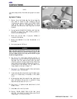
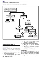
See Ignition Tests on following pages.
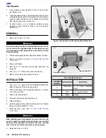
Use harness connector adaptor kit (HD-41404) gray
male probe and patch cord.
VOLTAGE AT TN/Y WIRE AT CONNECTOR [10B]
CONDITION
SIDESTAND
DOWN
SIDESTAND UP
Clutch Engaged
Transmission in Gear
<1.0V
12V
(Battery Voltage)
Neutral
Battery Voltage
minus 0.7V +/-
0.1V
12V
(Battery Voltage)
Clutch Disengaged
Battery Voltage
minus 0.7V +/-
0.1V
12V
(Battery Voltage)
Summary of Contents for 2002 P3
Page 2: ......
Page 17: ...A 15 Appendix A Tools HOME ...
Page 32: ...C 3 Appendix C Metric Conversions HOME ...
Page 41: ...1 8 2002 Buell P3 Maintenance HOME NOTES ...
Page 75: ......
Page 111: ...2 36 2002 Buell P3 Chassis HOME NOTES ...
Page 143: ...2 68 2002 Buell P3 Chassis HOME NOTES ...
Page 144: ...2002 Buell P3 Chassis 2 69 HOME ...
Page 146: ......
Page 147: ......
Page 223: ...3 76 2002 Buell P3 Engine HOME NOTES ...
Page 225: ......
Page 256: ...2002 Buell P3 Fuel System 4 31 HOME ...
Page 258: ......
Page 259: ......
Page 279: ...5 20 2002 Buell P3 Electric Starter HOME NOTES ...
Page 281: ......
Page 327: ......
Page 398: ...2002 Buell P3 Electrical 7 71 HOME ...
Page 400: ...Product 1 2 ...


