


2-52
2002 Buell P3: Chassis
HOME
SWINGARM
2.19
REMOVAL
1.
Remove seat. See
2.28 SEAT
.
2.
Remove battery. See
7.16 BATTERY.
1
1
WARNING
1
WARNING
Always disconnect the negative battery cable first. If the
positive battery cable should contact ground with the
negative cable installed, the resulting sparks may cause
a battery explosion which could result in death or seri-
ous personal injury.
3.
Remove right side footpeg support bracket. See
2.21
FOOTPEGS AND FOOTPEG SUPPORT BRACKETS
.
4.
Remove three bolts holding front sprocket cover. See
2.22 SPROCKET COVER
.
5.
Remove inner fender. See
2.23 FENDERS
.
6.
Remove lower belt guard. See
2.24 LOWER BELT
GUARD
.
7.
Remove rear axle nut, axle, spacers and brake with car-
rier. See
2.6 REAR WHEEL
.
8.
Remove drive belt. See
1.11 DRIVE BELT AND REAR
SPROCKET.
9.
Remove rear wheel. See
2.6 REAR WHEEL.
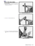
10. Remove lower rear shock fastener. See
2.15 REAR
SHOCK ABSORBER
.
11. See
Figure 2-92.
Loosen swing arm pinch bolt (1).
12. Remove swingarm pivot bolt (6) and swingarm.
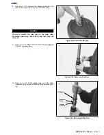
13. Remove well nuts from swingarm.
14. Use slide hammer (SNAP-ON Part No. CJ1275 or equiv-
alent) and bearing remover to remove bearings (4).
15. Remove swingarm spacer (5).
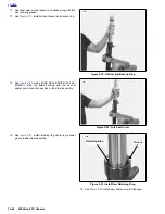
INSTALLATION
1.
See
Figure 2-92.
Install new bearings (4) and spacer (5).
2.
Position swing arm in mounting block. Apply anti-sieze to
swingarm bolt (6) and install. Torque to 24-26 ft-lbs (33-
35 Nm).
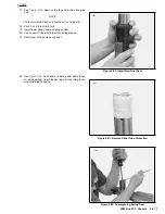
3.
Apply LOCTITE 243 BLUE to pinch bolt (1) and install.
Torque to 17-19 ft-lbs (23-26 Nm).
4.
Install well nuts.
5.
Install rear shock and fastener. Torque to 35-40 ft-lbs
(47-54 Nm).
6.
Install rear wheel, axle, brakes, and spacers. Torque rear
axle nut to 48-52 ft-lbs (65-71 Nm).
1
1
WARNING
1
WARNING
After completing repairs or bleeding the system, always
test motorcycle brakes at low speed. If brakes are not
operating properly or braking efficiency is poor, testing
at high speeds could result in death or serious injury.
7.
Install drive belt.
8.
Install rear fender, lower belt guard, and sprocket cover.
9.
Loosely install right side footpegs mount.
10. Install reservoir, master cylinder, and brake pedal.
Tighten brake pedal bolt to 6-8 ft-lbs (8-11 Nm).
11. Tighten footpeg mounting bracket.
12. Install battery. See
7.16 BATTERY.
1
1
WARNING
1
WARNING
Always connect positive battery cable first. If the positive
cable should contact ground with the negative cable
installed, the resulting sparks may cause a battery explo-
sion which could result in death or serious injury.
13. Install seat. See
2.28 SEAT.
1
1
WARNING
1
WARNING
After installing seat, pull upward on front of seat to be
sure it is locked in position. If seat is loose, it could shift
during vehicle operation, causing loss of control of vehi-
cle and death or serious injury.
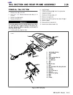
Figure 2-92. Swingarm
1
4
6
5
4
2
a0153x2x
1.
Pinch Screw
2.
Washer
3.
Nut Insert
4.
Bearing
5.
Spacer
6.
Pivot Bolt
3
Summary of Contents for 2002 P3
Page 2: ......
Page 17: ...A 15 Appendix A Tools HOME ...
Page 32: ...C 3 Appendix C Metric Conversions HOME ...
Page 41: ...1 8 2002 Buell P3 Maintenance HOME NOTES ...
Page 75: ......
Page 111: ...2 36 2002 Buell P3 Chassis HOME NOTES ...
Page 143: ...2 68 2002 Buell P3 Chassis HOME NOTES ...
Page 144: ...2002 Buell P3 Chassis 2 69 HOME ...
Page 146: ......
Page 147: ......
Page 223: ...3 76 2002 Buell P3 Engine HOME NOTES ...
Page 225: ......
Page 256: ...2002 Buell P3 Fuel System 4 31 HOME ...
Page 258: ......
Page 259: ......
Page 279: ...5 20 2002 Buell P3 Electric Starter HOME NOTES ...
Page 281: ......
Page 327: ......
Page 398: ...2002 Buell P3 Electrical 7 71 HOME ...
Page 400: ...Product 1 2 ...


