


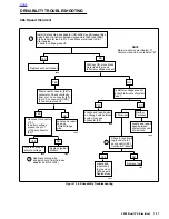


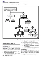


2002 Buell P3: Electrical
7-23
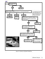
HOME
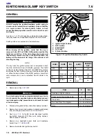
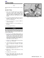
IGNITION COIL
7.9
GENERAL
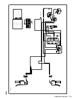
See
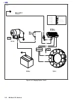
Figure 7-24.
The ignition coil is mounted on the frame
underneath the fuel tank on left side above airbox.
See
Figure 7-18.
The ignition coil is a pulse-type transformer.
Internally, the coil consists of primary and secondary wind-
ings with a laminated iron core. The contents are sealed in a
waterproof insulating compound. The ignition coil is not
repairable. Replace the unit if it fails.
The low-voltage ignition primary circuit consists of the coil pri-
mary winding, ignition module and battery. When the circuit is
closed, current flows through the coil primary winding creat-
ing a strong magnetic field in the iron core of the ignition coil.
When the ignition module receives a signal from the cam
position sensor and trigger rotor, the ignition module inter-
rupts (opens) the ignition primary circuit, which causes the
magnetic field in the coil core to collapse.
The collapsing magnetic field induces a high-voltage electri-
cal discharge in the ignition secondary circuit, which consists
of the coil secondary winding, spark plug cable and spark
plug. The high-voltage discharge produces a spark to bridge
the electrode gap of the spark plug.
The ignition coil fires the spark plug at the end of the com-
pression stroke (no-waste spark).
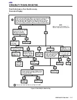
TROUBLESHOOTING
Follow the troubleshooting procedures listed under
7.8 IGNI-
TION MODULE/ CAM POSITION SENSOR
if the engine will
not start, is difficult to start or runs roughly. Also check condi-
tion of the spark plug cable. Insulation on cable may be
cracked or damaged allowing high tension current to short to
metal parts. This problem is most noticeable when cable is
wet.
If poor starting/running condition persists, check resistance of
ignition coil primary and secondary winding using an ohmme-
ter.
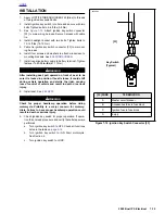
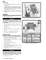
Ignition Coil Primary Circuit Test
1.
Remove ignition coil.
2.
Set ohmmeter scale to RX1.
3.
See
Figure 7-25.
Using harness connector adaptor kit
(HD-41404) gray female probes and patch cord, place
multimeter wires on primary coil windings. See Page 7-7.
4.
Check for primary coil winding resistance.
a.
Normal resistance range is 0.4-0.6 ohms.
b. See
TEST RESULTS
on the next page if resistance
is not within normal operating range.
Ignition Coil Secondary Circuit Test
1.
Remove ignition coil.
2.
Set ohmmeter scale to RX1K.
3.
See
Figure 7-26.
Using harness connector adaptor kit
(HD-41404) gray female probes and patch cord, place
multimeter wires on secondary coil windings. See Page
7-7.
4.
Check for secondary coil winding resistance.
a.
Normal resistance range is 7,720-9,440 ohms.
b. See
TEST RESULTS
on the next page if resistance
is not within normal operating range.
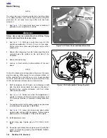
Figure 7-24. Ignition Coil (Left Side)
Figure 7-25. Ignition Coil Primary Resistance Test
7796
Spark Plug Post
Connector [83]
Mounting Screws (2)
7797
B
A
Summary of Contents for 2002 P3
Page 2: ......
Page 17: ...A 15 Appendix A Tools HOME ...
Page 32: ...C 3 Appendix C Metric Conversions HOME ...
Page 41: ...1 8 2002 Buell P3 Maintenance HOME NOTES ...
Page 75: ......
Page 111: ...2 36 2002 Buell P3 Chassis HOME NOTES ...
Page 143: ...2 68 2002 Buell P3 Chassis HOME NOTES ...
Page 144: ...2002 Buell P3 Chassis 2 69 HOME ...
Page 146: ......
Page 147: ......
Page 223: ...3 76 2002 Buell P3 Engine HOME NOTES ...
Page 225: ......
Page 256: ...2002 Buell P3 Fuel System 4 31 HOME ...
Page 258: ......
Page 259: ......
Page 279: ...5 20 2002 Buell P3 Electric Starter HOME NOTES ...
Page 281: ......
Page 327: ......
Page 398: ...2002 Buell P3 Electrical 7 71 HOME ...
Page 400: ...Product 1 2 ...


