


4-16
2002 Buell P3: Fuel System
HOME
5.
Verify that cables are seated in channel of throttle wheel,
and using cable adjusters at handlebar, tighten cables as
necessary to keep barrel ends from dislodging. Verify
operation by turning throttle grip and observing cable
action.
6.
Position cable clamp at top of cable bracket, so that short
end is above longer cable guide, long end above shorter
cable guide. With clamp capturing sleeves on cable
housings, tighten allen head screw to fix position.
7.
Install carburetor onto manifold-carburetor coupler. Turn
slotted screw to tighten band clamp on outboard side of
coupler.
8.
Mate pin and socket halves of 6-place Deutsch connec-
tor.
9.
Adjust throttle cables. See
2.16 THROTTLE CONTROL
.
10. Insert bolt through battery negative cable (black) into
threaded hole of battery negative (-) terminal. Tighten
bolt to 60-96
in-lbs
(7-11 Nm).
11. Adjust throttle position sensor. For instructions, see
4.6
THROTTLE POSITION SENSOR
, step 6.
12. Install air cleaner assembly. See
4.3 AIR CLEANER
steps 1-12.
13. Position seat on frame backbone, so that tongue at bot-
tom engages slot in frame weldment. Push down on rear
of seat until spring-loaded latch fully engages groove of
seat pin.
1
1
WARNING
1
WARNING
Pull up on seat to verify that it is properly secured, front
and rear. A loose seat may shift during vehicle operation
and startle the rider, possibly causing loss of vehicle
control that could result in death or serious injury.
14. Rotate handle of fuel valve to ON and carefully inspect
for leaks. Return the valve to the OFF position when fin-
ished.
15. Adjust engine idle speed. For instructions, see
1.19
IGNITION TIMING AND IDLE SPEED ADJUSTMENT
.
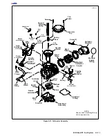
DISASSEMBLY - TOP END
1.
Remove gold Phillips screw (with top collar) to free throt-
tle cable bracket from carburetor top. Remove gold Phil-
lips screw (with lockwasher) at side of carburetor to
release throttle cable bracket. Set bracket aside.
2.
Remove three remaining top screws to release carbure-
tor top from body.
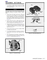
3.
Remove vacuum piston spring. Carefully raise dia-
phragm to remove vacuum piston assembly. Remove
spring seat and jet needle from vacuum piston bore. See
Figure 4-16.
Figure 4-15. Carburetor- Top End
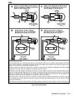
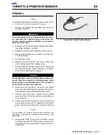
Figure 4-16. Remove Float Pin in Direction of Arrow
7754
Spring
Vacuum
Piston
Jet
Needle
Spring
Seat
a0183x4x
Arrow
Float Pin
Rounded
Pedestal
Summary of Contents for 2002 P3
Page 2: ......
Page 17: ...A 15 Appendix A Tools HOME ...
Page 32: ...C 3 Appendix C Metric Conversions HOME ...
Page 41: ...1 8 2002 Buell P3 Maintenance HOME NOTES ...
Page 75: ......
Page 111: ...2 36 2002 Buell P3 Chassis HOME NOTES ...
Page 143: ...2 68 2002 Buell P3 Chassis HOME NOTES ...
Page 144: ...2002 Buell P3 Chassis 2 69 HOME ...
Page 146: ......
Page 147: ......
Page 223: ...3 76 2002 Buell P3 Engine HOME NOTES ...
Page 225: ......
Page 256: ...2002 Buell P3 Fuel System 4 31 HOME ...
Page 258: ......
Page 259: ......
Page 279: ...5 20 2002 Buell P3 Electric Starter HOME NOTES ...
Page 281: ......
Page 327: ......
Page 398: ...2002 Buell P3 Electrical 7 71 HOME ...
Page 400: ...Product 1 2 ...


