


3-48
2002 Buell P3: Engine
HOME
OILING SYSTEM
3.12
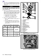
GENERAL
1.
Oil is gravity-fed from the oil reservoir to the gerotor-style
oil pump through a
feed hose.
Oil enters the
feed sec-
tion
and fills a cavity located under the feed pump.
NOTE
See
3.13 OIL PUMP
for a complete explanation of the gerotor
pump sets.
2.
The feed pump transfers oil from the inlet cavity through
the
external steel line
to the oil filter mount.
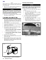
3.
Oil flows through the
filter mount cavity
to the oil filter.
4.
Oil enters the peripheral cavity of the
oil filter,
passes
through the filtering medium into the central cavity of the
oil filter, and flows into the filter adapter (fitting which
connects filter to filter mount).
5.
Adequate oil pressure in the filter mount cavity activates
the
oil pressure signal light switch
and shuts off the oil
pressure signal light.
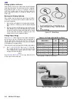
6.
Oil flowing from the filter adapter opens the
check ball.
The check ball opens at 4-6 psi (28-41 kPa) oil pressure.
7.
With the check ball open, oil flows into the
crankcase
feed galley.
8.
Oil flows through the feed galley in the crankcase to the
tappet blocks and hydraulic lifters.
Cross-drilled pas-
sages
intersect the main feed galley and carry oil to both
hydraulic lifters.
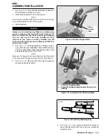
9.
Oil also enters an
intersecting passage
in the gearcase
cover. Oil flow is then routed to the crankshaft area.
10. Oil enters a hole in the end of the
pinion gear shaft
and
travels to the right flywheel where it is routed through the
flywheel to the
crankpin.
Oil is forced through the crank-
pin to properly lubricate the rod bearing assembly.
11. Oil flows up passages in the
push rods
to the rocker
arm shafts and bushings.
12. The valve stems are lubricated by oil supplied through
drilled oil holes in the
rocker arms.
13. Oil collected in the push rod areas of the cylinder heads
flows down the
push rod cover,
through drain holes in
the
tappet blocks
and into the gearcase. After providing
lubrication to the gearcase components, the oil flows to
the left side of the oil pump.
14. Feed oil to the rocker area is returned to the crankcase
through a
passage
in the head and cylinder.
15. Oil collected in the
sump
is splash-fed to the pistons,
cylinder walls and flywheel components.
16. A single piston oil jet cools the bottom of the piston with
a spray of oil.
17. Oil collected in the sump area returns to the scavenge
section of the oil pump through a
passage
located in the
rear section of the sump. Oil flow to the pump is accom-
plished by the scavenging effect of the pump and by the
pressure created by the downward stroke of the pistons.
18. Return oil fills a
cavity
above the pump's return gears.
The return gears pump oil back to the oil reservoir.
Summary of Contents for 2002 P3
Page 2: ......
Page 17: ...A 15 Appendix A Tools HOME ...
Page 32: ...C 3 Appendix C Metric Conversions HOME ...
Page 41: ...1 8 2002 Buell P3 Maintenance HOME NOTES ...
Page 75: ......
Page 111: ...2 36 2002 Buell P3 Chassis HOME NOTES ...
Page 143: ...2 68 2002 Buell P3 Chassis HOME NOTES ...
Page 144: ...2002 Buell P3 Chassis 2 69 HOME ...
Page 146: ......
Page 147: ......
Page 223: ...3 76 2002 Buell P3 Engine HOME NOTES ...
Page 225: ......
Page 256: ...2002 Buell P3 Fuel System 4 31 HOME ...
Page 258: ......
Page 259: ......
Page 279: ...5 20 2002 Buell P3 Electric Starter HOME NOTES ...
Page 281: ......
Page 327: ......
Page 398: ...2002 Buell P3 Electrical 7 71 HOME ...
Page 400: ...Product 1 2 ...


