


7-20
Confidential
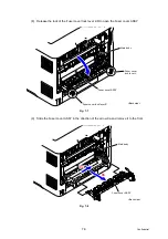
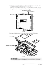
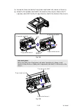
(14) In the case of model without touch panel, disconnect the three Connectors (CN5, CN6
and CN23) from the Main PCB ASSY and release the wiring.
In the case of model with touch panel, disconnect the three Connectors (CN5, CN6 and
CN18) from the Main PCB ASSY and release the wiring.
Fig. 7-33
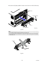
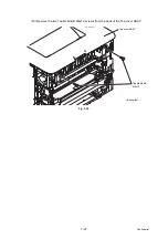
(15) Remove the Taptite cup S M3x8 SR screw from the front of the Top cover ASSY.
Fig. 7-34
Assembling Note:
Never fail to tighten the screw if the machine to be repaired is a model with a screw.
CN33 CN31
CN30
CN28 CN23
CN18
CN5
CN6
CN14
CN3
CN1
CN2
CN4
CN7
CN13
CN41
CN8
CN11
CN12
CN9
CN10
CN17
CN21
CN27
CN40
CN32
CN39
CN38
CN37
CN36
Main PCB ASSY
Model without touch panel only
Model with touch panel only
Taptite cup S M3x8 SR
Top cover ASSY
<Front side>


