


7-9
Confidential
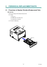
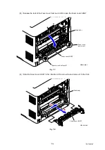
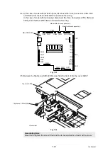
(16) Disconnect the two Connectors (CN1 and CN2) from the Eject sensor PCB ASSY.
Fig. 7-13
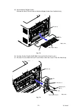
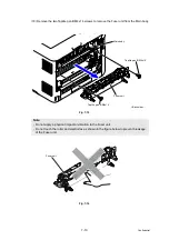
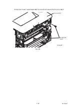
(17) Disconnect the Electrode terminal of the Main body from the Electrode terminal of the
Fuser unit.
Fig. 7-14
Assembling Note:
* Center thermistor has a black and blue connectors (230V models only).
The black connector may be connected to the blue insertion port and vice versa.
Connector
CN1
CN2
Eject sensor
Connector
CN1
CN2
<Back side>
PCB ASSY
*
(Center thermistor
harness
*
)
Fuser unit
Electrode terminal of the Fuser unit
Main body
Electrode
terminal
Main body
of the
<Back side>


