


3-46
Confidential
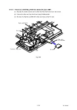
9.14 Top Cover ASSY
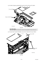
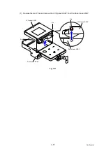
(1) Remove the four Screw bind M3x8 screws and remove the Main shield cover plate ASSY
from the Main body.
Fig. 3-45
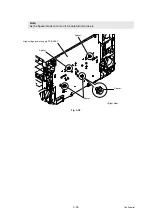
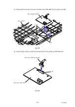
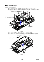
(2) In the case of model without touch panel, disconnect the three Connectors (CN5, CN6
and CN23) from the Main PCB ASSY and release the wiring.
In the case of model with touch panel, disconnect the three Connectors (CN5, CN6 and
CN18) from the Main PCB ASSY and release the wiring.
Fig. 3-46
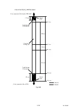
Note:
Note that the tightening torque is different between the upper side and lower side of
the Screw bind M3x8.
Upper side: 0.5±0.05 N
·
m
Lower side: 0.8±0.1 N
·
m
Main shield cover
Main body
<Left side>
plate ASSY
(Upper side)
(Lower side)
Screw bind M3x8
Screw bind M3x8
CN5
CN6
Main PCB ASSY
CN33 CN31
CN28 CN23
CN18
CN14
CN2
CN3
CN4
CN1
CN7
CN13
CN41
CN8
CN9
CN10
CN11
CN12
CN17
CN21
CN27
CN40
CN32
CN39
CN38
CN37
CN36
Model without touch panel only
Model with touch panel only


