2
Installation
9
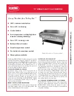
Blue Seal Evolution Series Gas Convection Ranges
© Copyright Moffat Ltd. 21 June 2016
Amendment 13
Assembly
All Models are delivered completely assembled. No further assembly is required. Refer to the information below for assembly
instructions.
NOTE:
All Models are delivered completely assembled. No further assembly is required. Refer to the information
below for assembly instructions.
This appliance is fitted with adjustable feet to enable the appliance to be positioned securely and level.
This should be carried out on completion of the gas connection. Refer to the ‘Gas Connection’ section.
Optional Accessories (Refer to Replacement Parts List)
Plinth Kit. For installation details, refer to the instructions supplied with each kit.
Rear Adjustable Legs.
1.
Check that all the feet (or castors) are securely fitted.
2.
Adjust the feet to make the convection oven range steady and level.
Gas Connection
NOTE:
ALL GAS FITTING MUST ONLY BE CARRIED OUT BY AN AUTHORISED PERSON.
1.
It is essential that the gas supply is correct for the appliance to be installed and that adequate supply pressure and volume are
available. The following checks should therefore be made before installation:-
a.
Gas Type
the appliance has been supplied for is shown on coloured stickers
located above the gas connection and next to the rating plate. Check that this is
correct for the gas supply the appliance is being installed for. The gas conversion
procedure is detailed in this manual.
b.
Supply Pressure
required for this appliance is shown in the ‘Specifications’
section of this manual. Check the gas supply to ensure adequate supply pressure
exists.
c.
The Input Rate
of this appliance is shown on the Rating Plate and in ‘Specifications’
section of this manual. The input rate should be checked against the available gas
supply line capacity.
Particular note should be taken if the appliance is being
added to an existing installation.
NOTE:
It is important that adequately sized piping runs directly to the connection joint on the appliance with as few tees
and elbows as possible to give maximum supply volume.
2.
Fit the gas regulator supplied, into the gas supply line as close to the appliance as possible.
NOTE: Gas pressure regulator provided with this appliance is convertible between Natural Gas and LPG and is already
converted ex-factory to the gas type labelled beside the gas connection point. The regulator outlet pressure is
fixed ex factory and it is NOT to be adjusted.
The regulator connections are
3
/
4
" BSP female.
The connection to the appliance is
3
/
4
" BSP male.
(Refer to the ‘Specifications’ section for the gas supply location dimensions).
NOTE:
A Manual Isolation Valve must be fitted to the individual appliance supply line.
3.
Correctly locate the appliance into its final operating position and using a spirit level, adjust the legs so that the appliance is
level and at the correct height.
4.
Connect the gas supply to the appliance. A suitable jointing compound which resists the breakdown action of LPG must be
used on every gas line connection, unless compression fittings are used.
5.
Check all gas connections for leakages using soapy water or other gas detecting equipment.
Rating Plate
Location
Fig 1
D
O
NOT
USE
A
NAKED
FLAME
TO
CHECK
FOR
GAS
LEAKAGES
.
Warning
Summary of Contents for Evolution Series
Page 94: ......