12
4. INSTALLATION
4. INSTALLATION
4. INSTALLATION
4. INSTALLATION
4. INSTALLATION
4.1 INSTALLATION CLEARANCES
4.1 INSTALLATION CLEARANCES
4.1 INSTALLATION CLEARANCES
4.1 INSTALLATION CLEARANCES
4.1 INSTALLATION CLEARANCES
Absolute care must be taken to ensure adequate air volumes on the condenser coil intake and delivery sides. It
is most important to avoid recirculation between the intake and delivery: failure to observe this prescription will
result in poor performance or interruption of normal operation . It is therefore necessary to observe the following
clearances:
- around the perimeter : a minimum distance of 1.5 or 1.8 metres according to the model. (see dimension sheets).
- top: make sure air expulsion is not impeded in any way.
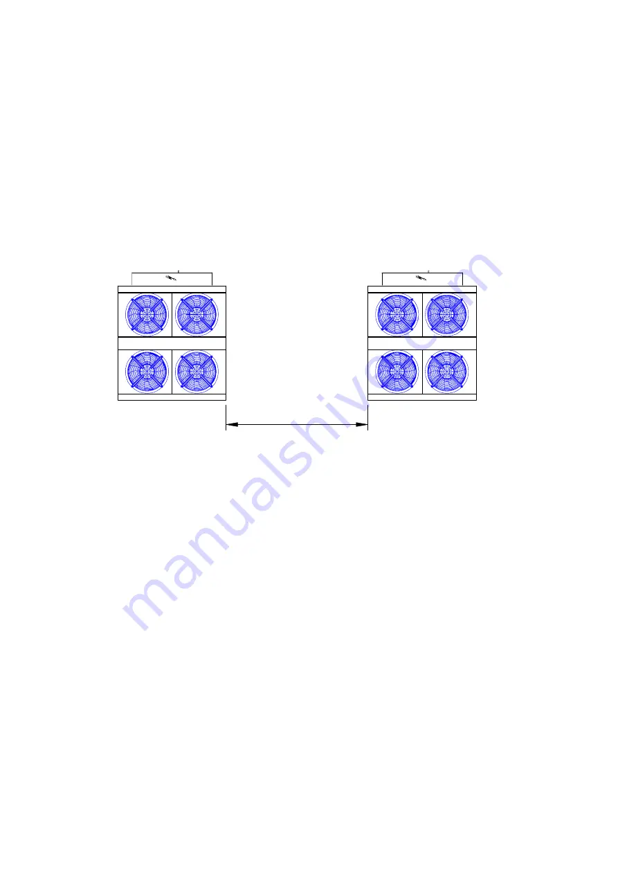
High walls (> 5 metres) near the machine may interfere with correct functioning. When units are side by side the
minimum distance between them should be 3 metres (see figure).
3 m
4.2 GENERAL RECOMMENDATIONS FOR WATER PIPE CONNECTION
4.2 GENERAL RECOMMENDATIONS FOR WATER PIPE CONNECTION
4.2 GENERAL RECOMMENDATIONS FOR WATER PIPE CONNECTION
4.2 GENERAL RECOMMENDATIONS FOR WATER PIPE CONNECTION
4.2 GENERAL RECOMMENDATIONS FOR WATER PIPE CONNECTION
Water pipelines must be installed in accordance with local and national rules and regulations (see charts enclosed
in this manual)
- Piping should be connected to the unit using flexible joints so as to avoid vibration and compensate for any
thermal expansion (adopt the same procedure for pumps)
- The following components should be installed on the pipelines:
- shut-off valves, temperature gauges and pressure gauges for regular maintenance and servicing.
- temperature probe sockets (if temperature gauges are not fitted).
- gate valves to separate the unit from the hydraulic circuit
- strainers (inlet pipes) with mesh no larger than 1 mm (obligatory in the case of plate type evaporators) to protect
heat exchangers from debris and foreign matter in pipelines.
- bleed valves installed on the upper parts of the circuit for venting of air.
- expansion tank with water filling group to maintain circuit pressure and to compensate for water thermal
expansion.
- drain cock and, where necessary, drainage tank for emptying the system during maintenance and seasonal
shutdowns.
- connection manifold between water in and out of evaporators (units with 2 independent evaporators, models:
32.2, 37.2, 50.2, 55.2), if not already ordered as option. Insert a pipe downstream the manifold to insert a
sensor to control the water leaving the chiller (option).
Summary of Contents for KAPPA V 2001
Page 69: ......


