


USER MANUAL 1.10 | DC1000 DIALOG-CONTROLLER
Berghof Automation GmbH | Harretstrasse 1 | 72800 Eningen | www.berghof.com
2VF100124FE08.docx | DC1000_HB_en_2D0982010ZD00.docx
87
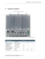
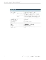
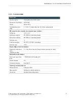
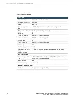
Digital output data
Module data
Number of outputs
8 (max. 12 if the I/O is used as an output)
Type of output
Semiconductor, non-saving
Protected circuit for inductive loads
Quick deactivation, 50 V terminal voltage (typical) against
+24 V
Power dissipation resulting from
deactivation
Max. 0.5 W / output; max. 4 W / module
Status indicator
None
Diagnostic function
None
Load connection
Total load (100%)
6 A (12 x 0.5 A)
Overload protection
Yes, for thermal overloads.
Activation of the thermal overload protection may influence
adjacent outputs.
Short circuit protection
1)
Activation threshold
Yes, electronic current limiter min. 0.5 A; typically 0.9 A.
1)
Current is electronically limited. Activation of the short circuit protection results in a thermal overload
which activates the thermal overload protection.
Output delay
from “0” to “1”
from “1” to “0”
Max. 0.5 ms
Max. 0.5 ms
Output capacitance
< 20 nF
Reference voltage
Voltage drop (at reference current)
DC +24 V
< 0.5 V
Reference current for “1” signal
Leakage current for “0” signal
0.5 A
Max. 0.1 mA
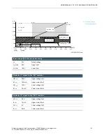
Total current, all outputs
(horizontal installation on vertical panel)
Max. 6 A (12 x 0.5)
Lamp load (DC +24 V)
Max. 6 W
Parallel switching of two outputs
for logical linkage
to increase performance
Permissible
Prohibited
Insulation resistance
Reference voltage
0 V < U
e
< 50 V
Test voltage up to an altitude of 2000 m
DC 500 V


