


USER MANUAL 1.10 | DC1000 DIALOG-CONTROLLER
Berghof Automation GmbH | Harretstrasse 1 | 72800 Eningen | www.berghof.com
2VF100124FE08.docx | DC1000_HB_en_2D0982010ZD00.docx
113
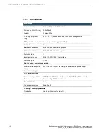
Digital inputs with counter-encoder function
The digital inputs I9-I16 (X2) can also be used as counter / encoder inputs. Each counting unit is connected
by means of two 24-V inputs. The digital status information of the inputs used as counters continues to be
available to the CODESYS PLC program.
Counting units
Number
4 counting units
Usage
Each counting unit can be used either as a quadrature decoder or
upward or downward counter.
Capture input
For each counting unit a digital input can be selected which triggers
capturing.
Maximum signal frequency
10 kHz (with a quadrature encoder this results in a 40 kHz counting
frequency)
Minimum pulse width
50 µs
Counter width
32 bit
WARNING
If overvoltage >32 V and / or energetic recovery occur, the module may be
destroyed.
This is a fire hazard!
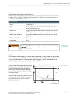
Outputs
The outputs are positive-switching, 24-V outputs. Output current max. 500 mA per output. The outputs have
a common reference potential (GND). Power is supplied together with the supply for the module electronics
(refer to ‘Terminal assignment’). If there is no data connection to the CPU or if the internal supply of the
module is inadequate, the outputs automatically switch to ‘0’ (LOW).
In case of overload the current is limited (typically
3 A). After the overload has been eliminated, the
output is available again. Fast de-excitation by
means of a 41-V terminal voltage in relation to L+
protects all outputs against induced peak voltages
with inductive loads.
If thermal loads occur owing to energetic recovery
or fast de-excitation, the overload protection may
react prematurely even in the case of outputs
which are not involved.
2VF100392DG01.cdr
IN
I
L
3-6 A
3 A
6 A
t
off(SC)
t
t
I
L(SCp)
I
L(SCr)
Turn on into short circuit
Digital outputs,
positive-switching
Protected output


