1523.5-0000010 OM
44
2.14 Switching of ranges and gears on GB 16
х
8
2.14.1 General information
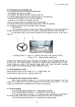
GB control is carried out with two levers: range shifting lever 1 (figure 2.14.1) and gear
shifting lever 3.
The required range or gear shall be set according to switching schemes 2 and 4, as it is
shown in figure 2.14.1.
1 – lever to switch ranges of gearbox; 2 – scheme of switching GB ranges; 3 – lever to
switch gears of gearbox; 4 – scheme of switching GB gears.
Figure 2.14.1 – GB 16
х
8 control
2.14.2 Velocity diagram of tractor with GB 16
х
8
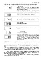
The table of “BELARUS-1523.5” tractor velocity diagram (figure 2.14.2) on tires of basic
configuration is attached to the cab right window.
Figure 2.14.2 – Velocity diagram of tractor “BELARUS-1523.5” with GB 16
х
8


