1523.5-0000010 OM
57
Your tractor can be equipped with two types of switching units - BK
А
-7.3722 or BK-1 which
are interchangeable.
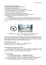
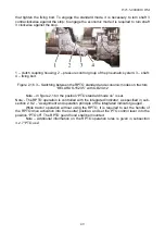
The place of unit 3 mounting is the cab, on the metallic bar of plastic shell fixing, between
instrument panel 4 and the windscreen.
To get an access to the relay and the fuses of unit 3, it is required to unscrew two quick-
detachable screws 1, then to remove plastic cap 2. The unit also has the protective plastic
casing for the protection from dust.
1 – screw; 2 – cap; 3 – switching unit; 4 – instrument panel.
Figure 2.20.1 – Switching unit mounting
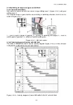
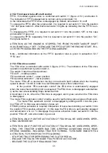
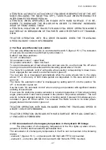
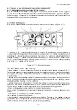
The unit consists of thirty cutout fuses 1 (figure 2.20.2) (FU1-FU30) and eighteen electro-
magnetic relays 4 (K1-K7, K9-K19, relay K8 is not mounted), commutating current supply
for consumers, a set of spare fuses 5. Signal led lamps of red color 2 located on the front
board near each fuse are intended for indication of a corresponding fuse blow out. A signal
led lamp of green color 3 indicates the switching unit turning on.
а
) BKA-7.3722
b) BK-1
1 – cutout fuse; 2 – signal led lamp of red color; 3 – signal led lamp of green color; 4 –
electromagnetic relay; 5 – set of spare fuses.
Figure 2.20.2 – Switching unit

