1523.5-0000010 OM
194
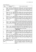
Table 6.12
Error
code
Description, possible
problem
Failure inspection method
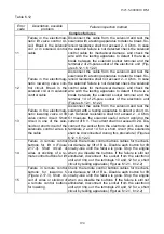
Complex failures
11
Failure in the electromag-
netic lift valve control cir-
cuit. Break in the solenoid
coil or in solenoid control
cable
Disconnect the cable from the solenoid and test the
solenoid with a testing apparatus to detect a break. So-
lenoid resistance shall not exceed 2...4 Ohm. In case
the solenoid failure is not detected check the solenoid
control cable for mechanical damage, and check the
wire with the testing apparatus to detect if there is a
break between the solenoid socket terminal and the
terminal 2 of 25-pole socket of the electronic unit (Fig-
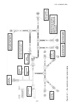
ures 6.12.1, 6.12.2)
12
Failure in the electromag-
netic lowering valve con-
trol circuit. Break in the
solenoid coil or in solenoid
control cable
Disconnect the cable from the solenoid and test the
solenoid with a testing apparatus to detect a break. So-
lenoid resistance shall not exceed 2...4 Ohm. In case
the solenoid failure is not detected check the solenoid
control cable for mechanical damage, and check the
wire with the testing apparatus to detect if there is a
break between the solenoid socket terminal and the
terminal 14 of 25-pole socket of the electronic unit
(Figures 6.12.1, 6.12.2)
13
Failure in the electromag-
netic lowering valve or lift
valve control circuit. Short
circuit in one of the sole-
noids or short circuit of the
solenoids control wires in
the cable
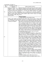
Disconnect the cable from the solenoid and test the
solenoid with a testing apparatus to detect a short cir-
cuit. Solenoid resistance shall not exceed 2...4 Ohm.
Or measure the solenoid useful current applying the
current of 6 V. The current shall not exceed 3.2A. Dis-
connect the socket from the electronic unit, check the
terminals 2 and 14 for a short circuit (the solenoids
shall be disconnected during this procedure) (Figures
6.12.1, 6.12.2)
14
Failure in remote control
buttons for lift 4 (Figure
2.17.3). Short circuit of
wires or sticking of a re-
mote control buttons for lift
Check the remote control buttons cables for mechani-
cal damage by lift of RLL. Disable each button for lift
one-by-one until the failure is gone. Stop the engine
when you disable the buttons. If the failure is still not
eliminated, disconnect the socket from the electronic
unit and ring out the terminals 10 and 12 for a short
circuit by testing apparatus (Figures 6.12.1, 6.12.2)
15
Failure in remote control
buttons for lowering 5
(Figure 2.17.3). Short cir-
cuit of wires or sticking of
a remote control buttons
for lowering
Check the remote control buttons cables for mechani-
cal damage by lift of RLL. Disable each button for lift
one-by-one until the failure is gone. Stop the engine
when you disable the buttons. If the failure is still not
eliminated, disconnect the socket from the electronic
unit and ring out the terminals 20 and 12 for a short
circuit by testing apparatus (Figures 6.12.1, 6.12.2)

