M‑3311A Instruction Book
6–4
Input
Number
Return
Terminal
Input
Number
1 (52b)
11
10
2
11
9
3
11
8
4
11
7
5
11
6
6
11
5
Table 6-2 Input Contacts
1. When
OUTPUT TEST (RELAY)
is
displayed press the right arrow to display
the following:
INPUT TEST (STATUS)
output INPUT led target
2. Press
ENTER
. The following is displayed:
INPUT NUMBER
1
3. Press
ENTER
. The following is
displayed:
INPUT NUMBER 1
CIRCUIT OPEN
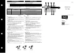
4. Connect
IN RTN
(terminal #11) to
IN1
,
(terminal #10). See Table 6-2, Input
Contacts.
5. Alternatively, if this specific input is
being used in the application, and the
external wiring is complete, the actual
external status input contact can be
manually closed. This will test the input
contact operation and the external wiring
to the input contacts. The following is
immediately displayed:
INPUT NUMBER 1
CIRCUIT CLOSED
6. Disconnect
IN RTN
(terminal #11) from
IN1
(terminal #10). The following is
immediately displayed:
INPUT NUMBER 1
CIRCUIT OPEN
7. Press
ENTER
. The following is displayed:
INPUT NUMBER
1
For units equipped with an optional HMI panel:
Following completion of testing, the output contacts,
can be turned
ON
in the following manner:
1. Press
ENTER
. The following is displayed:
RELAY NUMBER
1
2. Press
ENTER
. The following is
displayed:
RELAY NUMBER 1
OFF on
3. Use the right arrow button to change
“on” to uppercase letters, which signifies
selection. The following is displayed:
RELAY NUMBER 1
off ON
4. Press
ENTER
.
Output Relay
#1
will
energize.
The following is displayed:
RELAY NUMBER
1
5. Choose output numbers 2
-
9 (self-test)
(2-17 for extended version) by using
the up and down arrow buttons to turn
all relays or outputs to the energized or
ON
position. When each output is turned
on, the appropriate red
OUTPUT
LED
illuminates.
6.
Use the DMM to verify the position of
the output contacts in the energized or
ON
position. The readings should be
the opposite of the initial reading above.
All outputs should be returned to their
initial de-energized or
OFF
positions.
The
OUTPUT
LEDs will extinguish when
each output is turned off.
7.
If Output Relay testing is complete, press
EXIT
to return to the
DIAGNOSTIC
MODE
menu.
Input Test (Status)
The
INPUT TEST
menu enables the user to
determine the status of the individual status inputs.
For units equipped with an optional HMI panel:
Each input can be selected by number using the
up and down arrow buttons. The status of the input
will then be displayed.
Summary of Contents for M?3311A
Page 1: ...Instruction Book M 3311A Transformer Protection Relay ...
Page 30: ... 29 M 3311A Transformer Protection Relay This Page Left Intentionally Blank ...
Page 55: ...M 3311A Instruction Book 1 6 This Page Left Intentionally Blank ...
Page 87: ...M 3311A Instruction Book 2 32 This Page Left Intentionally Blank ...
Page 89: ...M 3311A Instruction Book 3 2 Figure 3 2 IPScom Main Screen ...
Page 107: ...M 3311A Instruction Book 3 20 Figure 3 22 Setup System Dialog Screen 2 3 Winding ...
Page 108: ...IPScom 3 3 21 Figure 3 23 Setup System Dialog Screen 4 Winding ...
Page 112: ...IPScom 3 3 25 Figure 3 29 I O Map Screen 4 Winding ...
Page 114: ...IPScom 3 3 27 Figure 3 31 Display All Setpoints Screen 4 Winding ...
Page 119: ...M 3311A Instruction Book 3 32 Figure 3 38 View Sequence of Events Recorder Screen ...
Page 127: ...M 3311A Instruction Book 3 40 This Page Left Intentionally Blank ...
Page 150: ...4 23 System Setup and Setpoints 4 Figure 4 14 Setup Sequence of Events Recorder Dialog Screen ...
Page 163: ...4 36 M 3311A Instruction Book Figure 4 15 IPScom Relay Setup System Dialog Screen 2 3 Winding ...
Page 166: ...4 39 System Setup and Setpoints 4 Figure 4 18 IPScom Selection Screen for Input Settings ...
Page 179: ...4 52 M 3311A Instruction Book Figure 4 28 Example of V Hz Capability and Protection Curves ...
Page 187: ...4 60 M 3311A Instruction Book Figure 4 33 49 Function Overload Curves ...
Page 229: ...4 102 M 3311A Instruction Book Table 4 5 Transformer Connections ...
Page 231: ...4 104 M 3311A Instruction Book Table 4 7 Custom Transformer and CT Configuration ...
Page 243: ...M 3311A Instruction Book 5 6 Figure 5 5 Mounting Dimensions for GE L 2 Cabinet H3 and H4 ...
Page 383: ...A 50 M 3311A Instruction Book This Page Left Intentionally Blank ...
Page 389: ...M 3311A Instruction Book B 6 This Page Left Intentionally Blank ...
Page 393: ...D 2 M 3311A Instruction Book Figure D 1 Volts Hz 24IT Inverse Curve Family 1 Inverse Square ...
Page 394: ...Inverse Time Curves Appendix D D 3 Figure D 2 Volts Hz 24IT Inverse Family Curve 2 ...
Page 395: ...D 4 M 3311A Instruction Book Figure D 3 Volts Hz 24IT Inverse Time Curve Family 3 ...
Page 396: ...Inverse Time Curves Appendix D D 5 Figure D 4 Volts Hz 24IT Inverse Curve Family 4 ...
Page 399: ...D 8 M 3311A Instruction Book Figure D 5 Definite Time Overcurrent Curve ...
Page 400: ...Inverse Time Curves Appendix D D 9 Figure D 6 Inverse Time Overcurrent Curve ...
Page 401: ...D 10 M 3311A Instruction Book Figure D 7 Very Inverse Time Overcurrent Curve ...
Page 402: ...Inverse Time Curves Appendix D D 11 Figure D 8 Extremely Inverse Time Overcurrent Curve ...
Page 439: ...F 28 M 3311A Instruction Book This Page Left Intentionally Blank ...