39214-208/Issue 2
39214-208/Issue 2
39214-208/Issue 2
1.
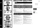
Activate the locking mechanism if the detector is to be locked into the
base. To do this, remove the small portion of plastic shown in
Fig 1
with
side cutters or similar tool.
2.
Partially screw two screws into the mounting box or soffi t at the required
centres. Place the corresponding slots of the base over the screws and
slide the base home. Tighten up the screws.
3.
Fig 1
shows the wiring terminals. The terminal marked ‘4’ on the base
is provided for con-
necting the screen
or functional earth.
4. The
outside
of
the
base is marked with
a moulded vertical
line to indicate the
position of the LED
when the detector
has been fi tted. This
facilitates detector
o r i e n t a t i o n i f r e -
quired.
5. When all the bases
have been fitted a
voltage test for wiring
co nt i n u i t y m a y b e
carried out. The base is fi tted with a continuity link which automatically
opens when a detector is fi tted to the base for the fi rst time.
6.
TimeSaver Base LX/TimeSaver Diode Base LX
These bases do not have the continuity link.
1.
Activate the locking mechanism if the detector is to be locked into the
base. To do this, remove the small portion of plastic shown in
Fig 1
with
side cutters or similar tool.
2.
Partially screw two screws into the mounting box or soffi t at the required
centres. Place the corresponding slots of the base over the screws and
slide the base home. Tighten up the screws.
3.
Fig 1
shows the wiring terminals. The terminal marked ‘4’ on the base
is provided for con-
necting the screen
or functional earth.
4. The
outside
of
the
base is marked with
a moulded vertical
line to indicate the
position of the LED
when the detector
has been fi tted. This
facilitates detector
o r i e n t a t i o n i f r e -
quired.
5. When all the bases
have been fitted a
voltage test for wiring
co nt i n u i t y m a y b e
carried out. The base is fi tted with a continuity link which automatically
opens when a detector is fi tted to the base for the fi rst time.
6.
TimeSaver Base LX/TimeSaver Diode Base LX
These bases do not have the continuity link.
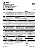
TimeSaver Base Wiring Guide
TimeSaver Base Wiring Guide
TimeSaver Base Wiring Guide
TimeSaver Base Wiring Guide
Fig 1
The Orbis base terminals
LED –
COM –
IN +
OUT
+
Terminal 4, Screen
(Functional Earth)
Direction of LED
indicated by mark
on outside of moulding.
Snip along marked lines and remove this
part to lock the detector to the base.
OUT +
LED –
IN &
OUT –
IN +
Fig 1
The Orbis base terminals
LED –
COM –
IN +
OUT
+
Terminal 4, Screen
(Functional Earth)
Direction of LED
indicated by mark
on outside of moulding.
Snip along marked lines and remove this
part to lock the detector to the base.
OUT +
LED –
IN &
OUT –
IN +
Fig 1
The Orbis base terminals
LED –
COM –
IN +
OUT
+
Terminal 4, Screen
(Functional Earth)
Direction of LED
indicated by mark
on outside of moulding.
Snip along marked lines and remove this
part to lock the detector to the base.
OUT +
LED –
IN &
OUT –
IN +
Fig 1
The Orbis base terminals
LED –
COM –
IN +
OUT
+
Terminal 4, Screen
(Functional Earth)
Direction of LED
indicated by mark
on outside of moulding.
Snip along marked lines and remove this
part to lock the detector to the base.
OUT +
LED –
IN &
OUT –
IN +