P
ULSAR
BG
Video Loop Through
Page 3
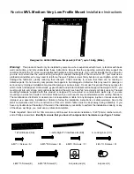
3 LAYOUT
MAIN
VID
EO
AUX
VID
EO
VIS
IF
SND
IF
COM
P
IF
VID
OUT
RF
OUT
IFs2
IN
IN
OUT
OUT
OUT
OU
T
IN
MAIN
AU
X
IN
IN
IN
REF
VID
AUX
IF
IF CW
REF
AUDIO
SUBC
AUDIO
INPU
TS
ST
AT
US &
CONT
ROL
FUSE
R
S
485
OUT
CIF IN
RF OUT
UP CONVERTER
CHANNEL FILTER
RF AMPLIFIER
POWER SUPPLY
MAIN BOARD
FREQ
LEVEL
MODE
SETTINGS
>
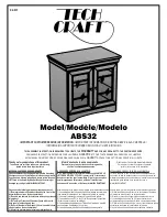
PULSAR
TV Modulator
SYSTEM
STATUS
LOCK
CONFIG
AUDIO
VIDEO
MODULATION
INPUT
AUX
AUTO
MAIN
RF TEST
-20 dB
ENTER
ESC
USER
U69
U7
U65
J61
J62
J5
3
J5
4
* Make the connections indicated with the
dashed lines when the option Main Scr/Aux
Unscr is installed. Otherwise make the
connections indicated with the full lines.
DC COUPLED
BR21
BR1
Cable 45
already installed
Cable 53
Cable 62*
already installed
Cable 61*
Summary of Contents for PULSAR BG
Page 2: ......
Page 6: ......
Page 10: ......
Page 12: ......
Page 36: ...Installation Filter Module PULSAR Page 6 2...
Page 42: ......
Page 47: ...PULSAR Audio Video Auxiliary Input Page 5...
Page 50: ......
Page 56: ......
Page 68: ......
Page 83: ...PULSAR BG Composite IF Aux Input Page 7...
Page 84: ......
Page 88: ......
Page 92: ......
Page 104: ......
Page 117: ...PULSAR BG Reference Carrier Output Page 3...
Page 118: ......