10. Expert operation
10.2.6 The Soft Edge selection dialog
Description
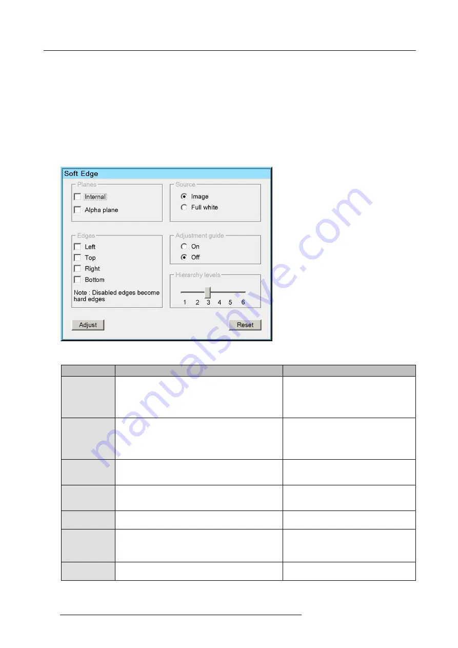
The Soft Edge selection dialog acts as a platform enabling you to give various inputs to the projector to perform soft edge adjustment.
It consists of the following sections:
•
Planes
•
Source
•
Edges
•
Adjustment guide
•
Hierarchy level
•
Action buttons
Image 10-45
The following table describes the
fi
elds in the Soft Edge selection dialog.
Field / button
Description
Notes
Planes
•
Internal
soft edge: to enable the Soft Edge or Blanking
area created through the OSD;
•
Alpha plane
: to enable an external Alpha plane that
has been uploaded to the projector.
Both
Internal
and
Alpha plane
can be selected
at the same time.
Source
•
Image
: to display the image of the selected source(s)
while adjusting the Soft Edge;
•
Full white
: to display full white while adjusting the Soft
Edge.
The procedures in this manual are explained
using a full white background.
Edges
In this section the edges of the total image where Soft
Edge blending needs to be applied must be selected:
Left,
Top, Right, Bottom
.
Disabled edges are hard edges. Adjusting a
hard edge results in creating a blanked area
without Soft Edge blending on that edge.
Adjustment guide
The adjustment guide consists of a four brightness
graduated bars applied on the selected edge(s).
The four bars coincide with the grid as
explained in "Soft Edge area shape", page
127.
Hierarchy level
The Soft Edge adjustment level can be set in a range from
one to six.
For more details, see "Soft Edge area shape",
page 127.
Reset
Click this button to return to the default Soft Edge settings,
i.e. on the selected edges, the Soft Edge shape follows the
active geometry settings and the width is set to 12.5%.
If starting to adjust Soft Edge from scratch, it is
a good practice to click
Reset
before clicking
Adjust
. Then you are sure that the Soft Edge
follows the active geometry settings.
Adjust
Click this button to display the Soft Edge edit dialog and
start de
fi
ning/adjusting Soft Edge or Blanking.
136
R5909056 MCM-400 HFR 11/05/2016
Summary of Contents for MCM-400 HFR
Page 1: ...MCM 400 HFR User Guide R5909056 02 11 05 2016 ...
Page 8: ...Table of contents 4 R5909056 MCM 400 HFR 11 05 2016 ...
Page 36: ...4 Facility and system requirements 32 R5909056 MCM 400 HFR 11 05 2016 ...
Page 53: ...6 Setup and configuration 5 Exit the menu R5909056 MCM 400 HFR 11 05 2016 49 ...
Page 60: ...6 Setup and configuration Image 6 19 56 R5909056 MCM 400 HFR 11 05 2016 ...
Page 62: ...6 Setup and configuration 58 R5909056 MCM 400 HFR 11 05 2016 ...
Page 86: ...7 Getting started 82 R5909056 MCM 400 HFR 11 05 2016 ...
Page 154: ...10 Expert operation Image 10 61 150 R5909056 MCM 400 HFR 11 05 2016 ...
Page 161: ...10 Expert operation Image 10 68 R5909056 MCM 400 HFR 11 05 2016 157 ...
Page 176: ...11 Maintenance 172 R5909056 MCM 400 HFR 11 05 2016 ...
Page 192: ...12 MCM 400 HFR tools 188 R5909056 MCM 400 HFR 11 05 2016 ...
Page 204: ...14 RCU Control 200 R5909056 MCM 400 HFR 11 05 2016 ...
Page 208: ...15 Environmental information Image 15 1 204 R5909056 MCM 400 HFR 11 05 2016 ...


