19
R5906852 /09
F80
shall be no lower than 2.5 meters above the floor. Horizontal clearance to the hazard distance zone shall be
not less than 1 meter. Alternatively, in case the height of the separation barrier for the horizontal clearance is
at least 1 meter high then the horizontal clearance (SW) can be reduced to:
•
0 meter if the height of the hazard zone is minimum 2.5 meter.
•
0.1 meter if the height of the hazard zone is minimum 2.4 meter.
•
0.6 meter if the height of the hazard zone is minimum 2.2 meter.
LIPs for installations in unrestrained environment (concerts, ...) shall be installed at a height vertically above
the floor such that the bottom plane of the Hazard distance Zone shall be no lower than 3 meters above the
floor. Horizontal clearance to the hazard distance zone shall be not less than 2.5 meters. Any human access
horizontally to the Hazard Zone, if applicable, shall be restricted by barriers. If human access is possible in an
unsupervised environment, the horizontal or vertical clearances shall be increased to prevent exposure to the
hazard distance zone.
The LIP shall be installed by Barco or by a trained and Barco-authorized installer or shall only be transferred to
laser light show variance holders. This is applicable for dealers and distributors since they may need to install
the LIP (demo install) and/or they transfer (sell, rent, lease) the LIP. Dealers and distributors shall preserve
sales and installation records for a period of 5 years. Variance holders may currently hold a variance for
production of Class IIIB and IV laser light shows and/or for incorporating RG3 LIPs. Laser light show variance
for RG3 LIPs can be requested by mailing the application to [email protected].
The installation checklist for laser illuminated RG3 projectors must be fully completed after the installation.
The installation checklist can be downloaded from the Barco website. The installer shall preserve the checklist
for a period of 5 years.
Install one or more readily accessible controls to immediately terminate LIP projection light. The power input at
the projector side is considered as a reliable disconnect device. When required to switch off the projector,
disconnect the power cord at the projector side. In case the power input at the projector side is not accessible
(e. g. truss mount), the socket outlet supplying the projector shall be installed nearby the projector and be
easily accessible, or a readily accessible general disconnect device shall be incorporated in the fixed wiring.
1.4.3 HD for fully enclosed projection systems
HD
Hazard Distance (HD) is the distance measured from the projection lens at which the intensity or the
energy per surface unit becomes lower than the applicable exposure limit on the cornea or on the
skin. The light beam is considered (to be) unsafe for exposure if the distance from a person to the
light source is less than the HD.
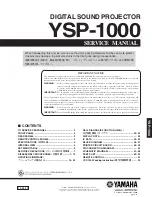
Restriction Zone (RZ) based on the HD
The projector is also suitable for rear projection applications; projecting a beam onto a defuse coated
projection screen. As displayed in
two areas should be considered: the restricted enclosed
projection area (RA) and the observation area (TH).
RA
TH
sw
PD
HD
DIFFUSE
s
w
RZ
s
w
s
w
PR
HD
REFLECTION
RESTRICTED
AREA
R
E
S
T
R
IC
T
E
D
A
R
E
A
Image 1–3
Summary of Contents for F80-Q12
Page 1: ...ENABLING BRIGHT OUTCOMES User Manual F80 ...
Page 22: ...R5906852 09 F80 22 Safety ...
Page 34: ...R5906852 09 F80 34 Getting Started ...
Page 44: ...R5906852 09 F80 44 Remote Control Unit ...
Page 56: ...R5906852 09 F80 56 GUI Introduction ...
Page 62: ...R5906852 09 F80 62 GUI Source ...
Page 78: ...R5906852 09 F80 78 GUI Image ...
Page 146: ...R5906852 09 F80 146 GUI System Settings ...
Page 156: ...R5906852 09 F80 156 Advanced Settings ...
Page 160: ...R5906852 09 F80 160 GUI Status menu ...
Page 176: ...R5906852 09 F80 176 Specifications ...
Page 181: ...181 R5906852 09 F80 Image B 1 HDCP revision information Connector specifications ...
Page 182: ...R5906852 09 F80 182 Connector specifications ...
Page 186: ...R5906852 09 F80 186 Control interface specifications ...
Page 194: ...R5906852 09 F80 194 Regulatory information ...
Page 205: ...205 R5906852 09 F80 DMX chart F ...
Page 209: ......