UMAX180800, 20 Thermocouple, 2 RTD, 4 Inputs, 6 Relays Dual CAN Controller
Version 1
Page: 36-71
Name
Default Value
Range
Units Description
Modbus Timeout
1000
1…10000
ms
The Modbus communication
timeout. Not used in the current
firmware.
Any updates to the function block configuration parameters will require a manual reset of the
controller to apply the new Ethernet settings.
3.18 CAN Input Signals
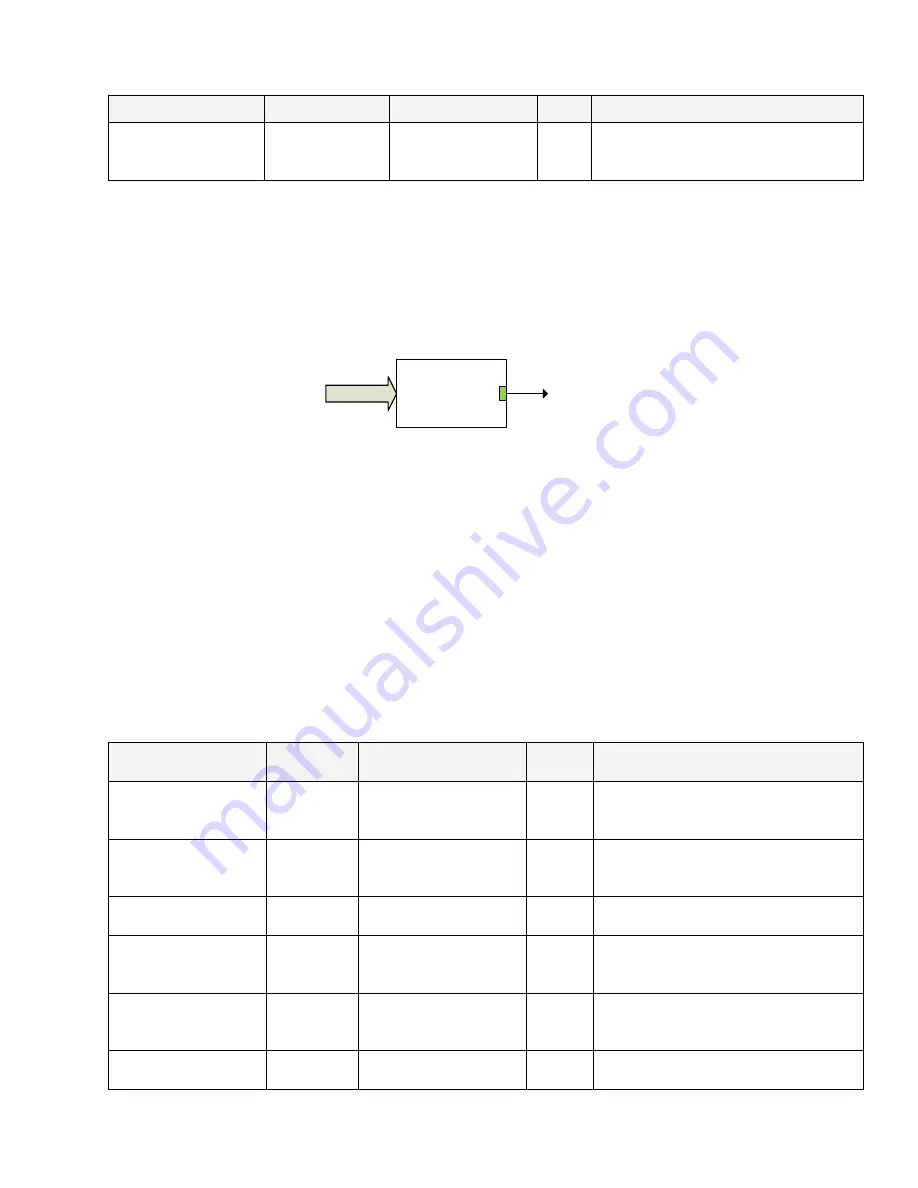
There are three
CAN Input Signal
function blocks available to the user. Each function block
represents one CAN input signal that can be received from the CAN bus. The function block
has one signal output.
CAN Input
Signal #1...3
Output
CAN Bus
Figure 9. CAN Input Signal Function Block
The
CAN Input Signal
function block reads single-frame application-specific CAN messages
and extracts CAN signal data presented in a user-defined data format. Different
CAN Input
Signal
function blocks can read and process the same CAN message to extract different CAN
signal data.
The CAN messages transmitted by the unit itself are also processed by
CAN Input Signal
function blocks. The only difference in processing of the internal messages is that they are not
sampled from the CAN bus and therefore their processing does not depend on the state of the
CAN bus.
Configuration parameters of the
CAN Input Signal
function block are presented below.
Table 34. CAN Input Signal Function Block Configuration Parameters
Name
Default
Value
Range
Units
Description
CAN Interface
1, CAN 1
0 - 3
–
Defines the CAN interface used to
send messages (CAN 1, CAN 2 or
Both)
Signal Type
0 -
Undefined
0 - Undefined,
1 - Discrete,
2 - Continuous
–
CAN input signal type
PGN
65535
Any J1939 PGN
value
1
–
Signal message PGN value
PGN From
Selected Address
0 - No
0 - No,
1 - Yes
–
Only CAN messages from the
selected address will be accepted,
if
“Yes”
Selected Address
0
0
…253
–
Address of the ECU transmitting
CAN messages if
PGN From
Selected Address
is set to
“Yes”
Data Position Byte
1
1
…8
–
Start byte of the CAN input signal
in the CAN message data frame


