UMAX180800, 20 Thermocouple, 2 RTD, 4 Inputs, 6 Relays Dual CAN Controller
Version 1
Page: 60-71
Data Size
0…32
0 bits
Refer to Section 3.19
Pos Byte
Depends on Source Selected 0
Refer to Section 3.19
Pos Bit
Depends on Source Selected 65,280
Refer to Section 3.19
Resolution
-100,000...100,000
1
Refer to Section 3.19
Offset
-100,000...100,000
0
Refer to Section 3.19
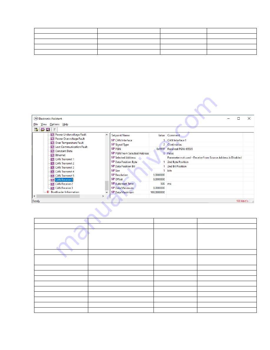
4.3.16 CAN Receive Setpoints
The CAN Receive setpoints are defined in Section 3.18. Refer to that section for detailed
information on how these setpoints are used. The screen capture below in Figure 28 displays
the available setpoints for the CAN Receive setpoints. Table 50 below highlights the allowable
ranges for each setpoint.
Figure 28: Screen Capture of Default CAN Receive Setpoints
Table 50. Default CAN Receive Setpoints
Name
Range
Default
Notes
CAN interface
Drop List
1, CAN Interface 1
Refer to Section 3.18
Signal Type
Drop List
0, Undefined
Default changed to
Contunious
for illustration
purposes. Refer to Section
3.18
PGN
0…65,535
65,535
Refer to Section 3.18
PGN From Selected
Address
Drop List
0, False
Refer to Section 3.18
Selected Address
0…255
1
Refer to Section 3.18
Data Position Byte
0…7
1
Refer to Section 3.18
Data Position Bit
0…7
1
Refer to Section 3.18
Size
0…32
0 bits
Refer to Section 3.18
Resolution
-
0xFFFFFFFF…0xFFFFFFFF
1.0
Refer to Section 3.18
Offset
-
0xFFFFFFFF…0xFFFFFFFF
0.0
Refer to Section 3.18
Autoreset Time
0...60,000
500
Refer to Section 3.18
Data Minimum
-
0xFFFFFFFF…Data Max
0.0
Refer to Section 3.18
Data Maximum
Data Min…0xFFFFFFFF
100.0
Refer to Section 3.18


