background image

Install the Inner Workings


Page | 48


9)


Figure 

10)


Figure 


Install the Inner Workings

48 


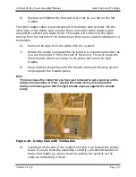
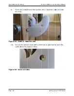
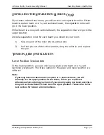
There is a small hole in the nautilus 
the hole

Figure 52 - Cable in Nautilus cam


Secure the 
cable above the copper crimp

Figure 53 - Secured Cable


Install the Inner Workings 


There is a small hole in the nautilus 
the hole.  

Cable in Nautilus cam

Secure the cable in place
cable above the copper crimp

Secured Cable


There is a small hole in the nautilus 

Cable in Nautilus cam

cable in place with a hitch pin by 

cable above the copper crimp

Secured Cable 


A


There is a small hole in the nautilus 

Cable in Nautilus cam 

with a hitch pin by 

cable above the copper crimp. 

A-Series Dobby Loom Assembly Manual


There is a small hole in the nautilus cam. Insert the cable end into 

with a hitch pin by placing it around the 

Series Dobby Loom Assembly Manual


Setting up the E

cam. Insert the cable end into 

placing it around the 


Series Dobby Loom Assembly Manual

Setting up the E-Lift Cables

cam. Insert the cable end into 


placing it around the 


Series Dobby Loom Assembly Manual 

Lift Cables 

cam. Insert the cable end into 

placing it around the 

Summary of Contents for A Series

Page 1: ...eries Dobby Loom Assembly Manual AVL Looms 2360 Park Avenue Chico CA 95928 6785 U S A 530 893 4915 530 893 1372 fax info avlusa com e mail www avlusa com v 1 1 Copyright 2019 All Rights Reserved Worldwide ...

Page 2: ......

Page 3: ...dle Pulley Support 12 24 Installation of the E Lift 26 Spring Lever Spring Perch Assembly 11 29 Squaring and Leveling the Frame 31 Install the Inner Workings 33 Harness Pulley Support 10 34 Dobby Head Installation 35 Treadle Tie Up 40 Setting up the E Lift Cables 45 Attaching the Harness Cables 49 Heddles 52 Installing Beams And Rollers 59 Warp Beams 60 Install the Lower Warp Beam 61 Install the U...

Page 4: ...lystring Tie Up 109 Two Box Flyshuttle Dropbox Movement 112 Four Box Flyshuttle Dropbox Movement 114 Finish Setting Up Your Loom 119 Compu Dobby Box 120 Mechanical Dobby Setup 123 E Lift Operation 124 Assembling the Bench 126 Appendix I Optional Equipment 129 Raddle 130 Tension Box 130 Auto Advance System 133 Locking Brake 136 Bustle 141 Appendix II Air Assist Options 143 Air Component Information...

Page 5: ...ts 16 Figure 16 Side Frame 17 Figure 17 Partially completed side frame 18 Figure 18 Top of side frame 19 Figure 19 Dobby Cam Assembly for E lift 20 Figure 20 Dobby Cam and Pulley for treadles 20 Figure 21 A Lift Pulleys 20 Figure 22 Lower Back Crossmember 21 Figure 23 Upper Back Crossmember 22 Figure 24 Loom on its back 22 Figure 25 Attaching front crossmember 23 Figure 26 Treadles 24 Figure 27 Tr...

Page 6: ...2 Figure 59 Parallel Harness Sticks 54 Figure 60 Harness Sticks with Heddles 54 Figure 61 Harness wire 55 Figure 62 Metal Heddle Frame 56 Figure 63 Beam Retainer 61 Figure 64 Warp Beam Handle 62 Figure 65 Lower Warp Beam Tension 64 Figure 66 Tension Arm Bolt 65 Figure 67 Lower Beam Tension Cord 66 Figure 68 Upper Position Tension 67 Figure 69 Tension Cable around Brake Drum 68 Figure 70 Upper Tens...

Page 7: ... Support 105 Figure 107 String tie up and handle 106 Figure 108 Vertical Pull Upper Pulley Assembly 107 Figure 109 Drop Box Assembly from Rear 108 Figure 110 Flyshuttle Box from back 109 Figure 111 Flyshuttle on cord 110 Figure 112 knot on flyshuttle cord 110 Figure 113 Routing Flyshuttle Cord 111 Figure 114 Spring and washer on Flyshuttle cord 112 Figure 115 Flyshuttle adjustment screw 113 Figure...

Page 8: ...e 138 A Lift Return Cable 149 Figure 139 Position the Pulley 149 Figure 140 Spring lever 150 Figure 141 Slide Plate Eyebolt and cable 151 Figure 142 Picker Stick Assembly 152 Figure 143 Picker Cylinder 153 Figure 144 Air Tubing Diagram 154 Figure 145 Piloted Valve right 155 Figure 146 Foot Pedal Error Bookmark not defined Figure 147 Shift Handle Switch 156 Figure 148 Safety Valve 157 Figure 149 Bi...

Page 9: ...A Series Dobby Loom Assembly Manual Introductory Information Introductory Information Page 1 INTRODUCTORY INFORMATION INTRODUCTORY INFORMATION ...

Page 10: ...FACTURING IF THE EQUIPMENT IS USED IN A MANNER NOT SPECIFIED BY THE MANUFACTURER THE PROTECTION PROVIDED BY THE EQUIPMENT MAY BE IMPAIRED WARNING ELECTRICAL SHOCK HAZARD DO NOT TAMPER WITH ELECTRICAL WIRES OR OPERATE THE LOOM WITH SAFETY PANELS OPENED OR REMOVED WARNING PINCH CRUSH AND FINGER CUT OFF HAZARDS DO NOT OPERATE THE LOOM WITH SAFETY PANELS OPENED OR REMOVED DO NOT PLACE HANDS IN MOVING ...

Page 11: ...TOPS OR ON OFF BREAKER SWITCHES WARNING USE OF CONDUCTIVE FIBER OR YARN ON OR AROUND THIS EQUIPMENT WILL VOID WARRANTY AND MAY DAMAGE EQUIPMENT WARNING THIS EQUIPMENT IS CLASSIFIED FOR LIGHT INDUSTRIAL ENVIRONMENT ONLY OPERATION OF HIGH CURRENT DRAW EQUIPMENT EX MIG WELDER ON THE SAME ELECTRICAL CIRCUITS MAY CAUSE EQUIPMENT FAILURE Safety Features Covers and shielding separate weaver from moving c...

Page 12: ...his manual Important information is pulled out into notes like this one Please review the notes when working on each section We have included many detailed drawings and photographs in this manual to help clarify our instructions Since not all of our parts are numbered you can use these drawings to help identify certain parts This manual includes assembly instructions for A Series looms The A serie...

Page 13: ...e System The Cloth Storage System consists of the Cloth Storage Beam the Cloth Storage Apron and the Cloth Advance Handle and pawl This system allows your woven cloth to be maintained under a separate tension from your warp Separation Roller You will have one of these rollers for each warp beam They serve to establish the warp in its horizontal plain Bottom Swing Beater The Bottom Swing Beater is ...

Page 14: ... Compu Dobby The Dobby Head works in tandem with the Compu Dobby and together they provide the interface between your computer and loom You can purchase the A Series loom with a mechanical dobby instead of the Compu Dobby In that case the assembly will be different Make sure you follow the instructions in the correct section on page 37 Treadles E Lift or A Lift The A series loom can come with trad...

Page 15: ...ill have 2 long springs per harness that attach directly to the harness For these looms you can have either standard or heavy duty springs BASICS OF ASSEMBLY For best results in assembling your loom please follow the detailed instructions in each section The following steps give an overview of the assembly process 1 Assemble each Side Frame The instructions start on page 16 2 Join the Side Frames ...

Page 16: ...that were not covered in the main manual check the appendix of optional equipment for instructions You will find instructions on using your new loom in the A series Weaving Manual Some of the features on AVL looms may differ from other looms you have used Please review the Weaving Manual before beginning to use your loom THE LOOM On the next two pages are pictures of the full loom Depending on the...

Page 17: ...A Series Dobby Loom Assembly Manual Introductory Information the Loom Page 9 Figure 1 Full Loom Left Side ...

Page 18: ...Introductory Information A Series Dobby Loom Assembly Manual Page 10 the Loom Figure 2 Full Loom Right Side ...

Page 19: ...A Series Dobby Loom Assembly Manual Frame Assembly Frame Assembly Page 11 FRAME ASSEMBLY FRAME ASSEMBLY ...

Page 20: ...drawing This symbol shows a weaver seated at the weaving bench The symbol is included only to help clarify the orientation of the drawing In this example the weaver is sitting looking toward the right of the page That would indicate that the front of the loom is to the left of the page and the rear of the loom to the right If the arrow were pointing left then the rear of the loom is to the left Th...

Page 21: ...ons will take two people to complete For protection in shipping packing materials of several sorts are used around the pieces of your loom Check the packing materials carefully for loom parts You may want to keep all the shipping materials until the loom has been put together to make sure nothing is lost The boxes your loom comes in are custom made for shipping your loom If you have space to store...

Page 22: ...he wood Figure 5 Carriage Bolt These never get a washer between the head of the bolt and the wood Figure 6 Flat Head Machine Screw You may not have machine screws depending on the options of your loom Figure 7 Flat Washer Figure 8 Hex Nut These always have a washer between the nut and the wood and they attach to hex bolts or carriage bolts Figure 9 Square Nut These always go in a nut access hole T...

Page 23: ...cess hole NOTE Given the limited space provided by the nut access holes it can be challenging at first getting the nuts onto the bolt ends You ll find it helpful to push each bolt in just until it just appears in the access hole Move the nut into position over the end of the bolt and hold it with your finger Slowly turn the bolt clockwise and when the nut engages tighten it most of the way down If...

Page 24: ...the round portion is flush with the surface They often require a tap or two from the hammer to seat the square part of the bolt s head into the wood Figure 15 Inserting Nuts SIDE FRAME ASSEMBLY The Side Frames for the loom are shipped disassembled They must be assembled properly for the loom to operate You will want to refer to the Side Frame illustrations periodically to check the assembly Pieces...

Page 25: ...f the pieces and will not be visible when the loom is completed The picture below has numbers added for Left side with attached tool holder Bottom Horizontal Lower Cloth Beam Support Side Support one with bracket one without Beam Support not numbered but marked with L or R The numbers are located on the edges of the pieces and will not be visible when the loom is completed The picture below has nu...

Page 26: ...ith washers and nstructions once for each side you just removed on the right side and half on the left side 1 2 bolts attach the front vertical 1 4 making sure that the nut access positioned on the rear vertical 2 to the rear 1 2 long the side support 9 with the bracket already attached to it bottom horizontal The bracket should be to the inside of the loom the side support 9 without the bracket w...

Page 27: ...to the front vertical 1 with a 5 Dobby Cam and Pulley 20 The Dobby Cam and Pulley assembly will be plac between the 9 supports This assembly allows the treadles or e support through the front h of the side supports er cloth beam support with one 5 16 x 5 bolt through the Attach it into the e lower cloth beam support 1 with the number stamp on it must be with one bolt with the number stamp facing d...

Page 28: ...ift and the dobby They will be installed later the dobby cam and pulley assembly in the hardware package loosen remove them Dobby Cam Assembly for E lift holes in the right Make sure one support is loose enough to pivot slightly through the hole so that the dobby cam and pulley are Pivot the support enough to push the rod Depending on your loom options you will have one of the Dobby Cams If you ha...

Page 29: ... insert the rest of the beams Tighten the bolts in the order shown in the instructions the upper back 5 and right side between Using four 5 16 x 3 1 4 hex bolts attach the nuts started Lower Back Crossmember Slide the rod through the hole on the the stop collars on the rod outside the supports Using the Allen wrench tighten the stop collar frames are complete you will need to complete the frame by...

Page 30: ... 5 16 x 3 There are If you have a treadle loom there will be some hardware Since the nut access holes are on the bottom of this piece you will need to its back for easy access Please use care when doing this A Series Dobby Loom Assembly Manual between the left and right side frames four 5 16 x 3 1 4 hex There are nut access holes on the bottom If you have a treadle loom there will be some hardware...

Page 31: ...es on the loom Remove both blocks and separate the rod hole is off set slightly away reassemble the Your loom will have treadles an E ctions in this section For an E section starting on page 24 Instructions on the loom From the outside of the loom insert the bolts into the holes in the left side fra 1 4 hex bolts in the right side frame through the lower front attach the nuts and tighten Attaching...

Page 32: ...p the treadle end blocks onto each end of the rod The order of parts in the assembly now should be as follows from left to right a left mounting block b left treadle the long one c two spacers d right treadle e right mounting block Figure 26 Treadles 4 You can now bolt this treadle assembly to the top face of the lower front and gently set the front of the loom back down on the floor TREADLE PULLE...

Page 33: ...BOTTOM FRONT are on the front piece facing down and on the right side of the loom This should put the two rods a little bit closer to the right side of the loom Figure 27 Treadle Pulleys 3 Insert the 5 16 x 3 1 4 hex bolts with washers through the corresponding holes in the vertical support assembly 9R and 9L attach square nuts and tighten securely A Lift or E Lift Equipped Looms The 12 Lift Suppo...

Page 34: ...shers through the corresponding holes in the vertical support assembly 9R and 9L attach square nuts and tighten securely INSTALLATION OF THE E LIFT The E Lift replicates the action of treadling When you activate the foot switch the motor turns and selected harnesses rise or fall The motion is smooth quick and precise and does not jar the harnesses Review Contents and Hardware Please check that you...

Page 35: ...mbly Manual Motor Controller Assembly Lift will be mounted to the 12 Lift under the cross Lift mounting plate with the vertical holes in Controller Assembly Lift will be mounted to the 12 Lift under the cross members to align the holes in the Lift mounting plate with the vertical holes in Controller Assembly Lift will be mounted to the 12 Lift Support members to align the holes in the Lift mountin...

Page 36: ...uple of pieces of 2 x 4 to help elevate it into position while getting the From the top of the cross member p into each of the four holes and let them hang with the exposed ends pointing to the floor Thread a mounting block onto each set of bolts and then engage the bolts in the corresponding holes in the E A Series Dobby Loom Assembly Manual Lift power switch faces to the rear of the l and the ro...

Page 37: ...E lift installed SPRING LEVER SPRING PERCH ASSEMBLY 11 8 16 24 Harness Equipped Looms 1 Find the spring lever assembly This assembly consists of two long pieces attached by rods with many short thin rectangular spring levers between 2 Place this assembly so that the stamp BOTTOM FRONT is on the front facing the floor and on the right side of the loom 3 Using four 5 16 x 3 1 4 hex bolts washers and...

Page 38: ...arness Equipped Looms 1 Find the spring perch assembly This assembly consists of two wood cross members with spring perch with 64 or 80 eye hooks attached spanning between the two boards 2 Place the assembly so that the quarter circle cut out faces forward and down 3 Using four 5 16 x 3 1 4 hex bolts washers and square nuts attach the spring lever assembly between the side frames a foot or so abov...

Page 39: ...rame is square and level Please make a note of this process as it is an important part of the maintenance of your loom Your loom will perform better and give years of service if this process becomes a part of your regular loom Using a tape measure note these measurements are measuring from the same place on the loom on both sides The distance from the inside corne L to the inside corner of the Fro...

Page 40: ...rder to achieve Once the loom is square and level check and tighten all bolts and nuts that connect the frame pieces Over time due to the shaking and movement the loom experiences during use these connections will shake loose requiring periodic checking and tightening Make a check of these components A Series Dobby Loom Assembly Manual Squaring and Leveling the Frame to use shims under the four co...

Page 41: ...A Series Dobby Loom Assembly Manual Install the Inner Workings Install the Inner Workings Page 33 INSTALL THE INNER WORKINGS INSTALL THE INNER WORKINGS ...

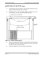
Page 42: ...ween two long cross members 2 Find four 5 16 x 7 1 2 hex bolts washers and hex nuts You ll need washers under the hex bolts and the hex nuts Figure 37 Harness Pulley Support 3 Place the harness pulley support so that the left side is flush with the left side of the loom and the right side sticks out a few inches beyond the right side frame pieces 4 Attach the support to the loom frame with the bol...

Page 43: ...l arrive in a separate box The dobby is the dobby head wood back plate with attached slide plate gray metal box with solenoids thumbscrews on the sides of the solenoid box and lift it off The cables on the dobby head correspond to the harness cables closest to the front of the loom corresponds to the first the cable farthest to the right closest to the back of the Please note your dobby head will ...

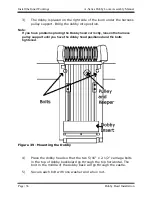
Page 44: ...ou have problems placing the Dobby head correctly loosen the harness pulley support until you have the dobby head positioned and the bolts tightened Figure 39 Mounting the Dobby 4 Place the dobby head so that the two 5 16 x 2 1 2 carriage bolts in the top of dobby backboard go through the top horizontal The bolt in the middle of the dobby back will go through the castle 5 Secure each bolt with one...

Page 45: ...through the attached harness cables all the way down to the harness spring system Should you find incorrect harness selection by the Compu Dobby the cause is often due to harness float To address simply increase harness spring tension by incrementally shortening up on the links at the spring lever or for 32 and 40 harness looms by adding a set of heavy duty or second set of standard harness spring...

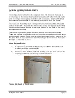
Page 46: ... 1 2 carriage bolts in the top of dobby backboard go through the top horizontal The bolt in the middle of the dobby back will go through the castle 5 Secure each bolt with one washer and a hex nut Mounting the Dobby Arm 19 1 Lift the dobby arm and support into place 2 Using the 5 16 x 2 3 4 hex bolts provided attach the dobby arm support to the outside of the right top horizontal The heads of the ...

Page 47: ...ur unit against are in their Left side of the Mechanical Dobb Series Dobby Loom Assembly Manual shipping the springs against the following figure their proper Left side of the Mechanical Dobb springs on the the following figure place Left side of the Mechanical Dobb the dobby head the following figure to Left side of the Mechanical Dobby with springs Install the Inner Workings head come to make su...

Page 48: ...p this section and move on to the next section on setting up the e lift cables Left Treadle 1 There are two cables coming out of the bottom of the dobby head 2 Take the longest one and run it down to and under the groove of the pulley nearest to the rear of the loom in the dobby cam and pulley assembly Figure 42 Dobby Cam and Pulley ...

Page 49: ...e large access hole near the far end of each treadle Remove the nut from the bolt in the left treadle 5 Back the bolt out so that the end of the bolt is at about the middle of the large access hole Figure 44 Bolt for the Treadle Cable 6 Now slip the loop of the long cable you have just routed over the pulley over the end of the bolt 7 Push the bolt back in and tighten the nut with a wrench With th...

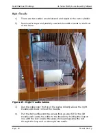
Page 50: ... and taped to the cam and partially unwind the Right Treadle Cables over the top of the pulley directly above the right the treadle Pull the bolt out beyond the access hole as you treadle and secure the cable to the treadle line with the bolt inside the access through the loop and on through the treadle A Series Dobby Loom Assembly Manual around and taped to the cam and partially unwind the cable ...

Page 51: ... clockwise direction as you are looking at it from the rear of the loom This will cause the short treadle cable to wind up on its pulley and raise the right treadle 8 Keep rotating the pulley until the treadle comes all the way up and stops against the treadle pulley Note This may cause the cable that you have just released to get wound up on the dobby cam assembly If it has unwind the cable while...

Page 52: ...to the dobby cable eyebolt Note The purpose of the turnbuckle is to give a way to adjust treadle travel so that you get a full shed 12 In order to get the proper adjustment you ll need to tighten or loosen the turnbuckle until when the left treadle is pushed all the way down the slide plate raises and touches the upper bumpers in the dobby box 13 At this point the short treadle should stop about 1...

Page 53: ...n move on to the next section Installing the Cam Pulley Cables 1 There is a cable wrapped around the cam pulley that will go to the dobby slide plate Route the cable around and under the pulley then up the outside of the loom to the dobby slide plate Figure 47 Cam Cables 2 Slip the cable end through the hole in the bottom plate and connect the cable end to the lower eyebolt on the slide plate Figu...

Page 54: ...Tighten the stop collars The dobby slide plate to spring lever cable is attached to the slide plate with a quicklink in the eyebolt on the upper back right corner of the slide plate The cable goes over a small white plastic pulley with a retainer above it Figure 49 Dobby Slide Plate to Spring Lever Cable 4 The cable will go down the right side of the dobby back Guide the cable around the bottom of...

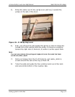
Page 55: ...pring in order to bring the looped end of the cable around the pulley on the lever and back toward the right side of the loom to anchor it at the open J Bolt Note You can also remove the spring and replace it once the cable has been anchored on the J bolt 7 Remove the tape from the E Lift motor to cam cable which is wound around the cam at the top of the E lift 8 Take the cable and guide the free ...

Page 56: ...m cable in place with a hitch pin by cable above the copper crimp Secured Cable A There is a small hole in the nautilus Cable in Nautilus cam with a hitch pin by cable above the copper crimp A Series Dobby Loom Assembly Manual There is a small hole in the nautilus cam Insert the cable end into with a hitch pin by placing it around the Series Dobby Loom Assembly Manual Setting up the E cam Insert t...
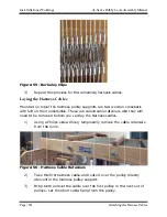
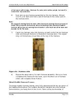
Page 57: ...Clip opened with pliers ARNESS CABLES For some of the steps in this process you will need to access the top of the loom You may need a small ladder or step stool The Harness Cable has three ends two that end with loops and one with a with loops support the harness The longer side goes to the left side of the harness and the shorter one is for the right side The clip attaches to the corresponding c...

Page 58: ...port both ends of the cable over short cable hang A Repeat this process for the remaining harness Mounted on top of the harness pulley supports are two wooden These are called cable retainers and they will need to be removed before you can lay the harness cables screwdriver temporarily remove Harness Cable Retainers harness cable and route in the harness pulley support cable over the short cable h...

Page 59: ...ness cables are over all of the pulleys 6 After all cables are in place on each pulley check to see that no cables have crossed over each other 7 Replace the cable retainer above the right set of pulleys tightening the screws so that it almost touches the pulleys Note It is essential to the proper functioning of the loom that the cables be free to move The cable retainer s purpose is to keep the c...

Page 60: ...les please use our website www avlusa com or call us at 530 893 4915 Number of Harnesses Heddles per loom 8 800 16 1600 24 2400 32 3200 40 4000 Polyester Heddles The polyester heddles come attached to each other and will need to be cut apart The heddles are shipped in bundles of 100 There are two twist ties on the bottom and two twist ties on the top Figure 58 Polyester Heddle Bundle These go thro...

Page 61: ... 40 harness looms the bottom sticks are all the same Note The bottom harness sticks marked 1 go to the front of the loom and the sticks marked 2 go to the back of the loom We suggest you place the harnesses on the loom starting from the back The heddles need to be placed on the harnesses and the complete harness placed on the loom We suggest you assemble the harnesses on a table Note The polyester...

Page 62: ... remove the twist ties and spread the heddles out If you have not cut the heddles apart yet you will need to do that now Note If you want to color code your heddles this would be a good time Take a colored marker and color the eyes of all the heddles on a harness so that you can easily tell what harness you are threading For instance you may use four colors of pen and mark the eyes on the heddles ...

Page 63: ...orking from Bundle 1 is for the front of the loom and bundle 2 is for the back 7 Insert one harness wire into the hole at each end of the top harness stick and through the hole in the bottom harness stick The copper stop on the harness wire will be at the top of the harness Figure 61 Harness wire 8 Repeat the steps above for each harness assembly Once you have completed the frames for the back ope...

Page 64: ...connecting them to the waiting ends of the harness cables Note which harness stick is the top before placing it Figure 62 Metal Heddle Frame Spring Installation 8 16 24 Harness Equipped Looms These looms have the spring lever system You will have a wooden lever with a chain on one side and a hook the other The chains will connect to the harnesses The levers are connected with a spring between the ...

Page 65: ... wire hook When you put your first warp on adjust the tension with the chain 32 40 Harness Equipped Looms Looms with 32 or 40 harnesses will have a system of springs that attach in a V shape 1 After the harnesses are hung on the loom find the harness springs 2 Starting with the rear most springs attach the springs to the eye hooks on the bottom of the harness sticks ...

Page 66: ......

Page 67: ...A Series Dobby Loom Assembly Manual Installing Beams And Rollers Installing Beams and Rollers Page 59 INSTALLING BEAMS AND ROLLERS INSTALLING BEAMS AND ROLLERS ...

Page 68: ...r position you will have a brake cable marked 38P For a 1 yard sectional beam in the upper position you will have a brake cable marked 38S You can order the A series loom with a three beam system In this case you can use a yard sectional or plain beam in any position You cannot use a one yard sectional beam with the three beam system In either of the above options installing the beams and tension ...

Page 69: ...he warp beam and with the large round wooden drum to the left side of the loom seat the beam axle into the slots 2 Swing the retainers around to hold the beam Figure 63 Beam Retainer 3 When the latches have captured the axle and are in a vertical position tighten them down Warp Beam Handle 1 Find your warp beam handle 42 2 Remove the wing nut washer and bolt from the end of the handle 3 Place the ...

Page 70: ...ctional beam it can only be placed in the upper position You can also install a second plain beam or yard sectional beam in the upper position 1 Lift the warp beam and with the drum to the left side of the loom seat the beam axle into the slots 2 Swing the retainers and when they have captured the axle and are in vertical position tighten them down 3 Install the Warp Beam Handle Note If you are us...

Page 71: ... loom 1 Slip one end of the roller into its pinned slot 2 Pull the pin out of the other bracket drop the roller in and replace the pin TENSION ARM INSTALLATION Lower Position Tension Arm In the lower position you can only have a plain warp beam or a yard sectional warp beam The brake cables for the upper and lower position are different Note If you only have one beam and it is a plain or yard sect...

Page 72: ...and place it so that the face of the pulley lies against the inside of the left rear vertical Figure 65 Lower Warp Beam Tension 2 Remove the long bolt from the pulley end of the tension arm 3 Keeping one washer on the bolt push the bolt through the lower hole in the rear vertical from the outside for the plain beam If you ...

Page 73: ...hing onto the bolt 5 Add another washer and the hex nut and tighten it down 6 After tightening check to make sure the arm swings freely Now the cord tie up can be attached Attach the tension arm cord 1 Find the tension arm cord labeled 16 2 Attach this cord to the tension arm by removing the shoulder bolt the bolt near the wooden pulley using a 5 32 Allen wrench and place this bolt through the loo...

Page 74: ... assembly is an eyebolt 2 Remove one hex nut and washer from the eyebolt and insert it from the inside of the loom through the hole in the upper rear portion of the left bottom horizontal Figure 67 Lower Beam Tension Cord 3 Replace the hex nut and washer on the outside of the loom and tighten the eyebolt placing it so that it sets as far inward as possible No threads should protrude beyond the nut...

Page 75: ... cord marked 38P Otherwise the setup is the same Note If you have a three beam system install the upper tension arm so that it is on the outside of the loom rather than the inside The hole for the tension cord eyebolt will be marked as it is further toward the front of the loom 1 Find the tension arm and place it so that the face of the pulley lies against the inside of the left rear vertical Figu...

Page 76: ...n 6 After tightening check to make sure the arm swings freely Attach the Tie up Cord or Cable 1 Find the tension arm cable 38S for the one yard sectional beam or the tension arm cord 38P for the yard sectional or plain beam 2 Attach the cable or cord to the tension arm by removing the shoulder bolt the bolt near the wooden pulley using a 5 32 Allen wrench and place this bolt through the looped end...

Page 77: ...lt 2 Remove one hex nut and washer from the eyebolt and insert it from the inside of the loom through the hole at the very back of the upper left horizontal frame piece Figure 70 Upper Tension Tie up 3 Replace and tighten the hex nut and washer on the eyebolt Tension Arm Weight Instructions The tension arm weight provides the weight for the tension arm assembly allowing you to easily adjust the te...

Page 78: ...d 3 Position the weight so that the knobs will be accessible to you 4 Slide the wooden bracket and bolts back through the weight the arm should be in between the weight and bracket Figure 72 Tension Arm with Weight 5 Re attach the two black knobs and tighten down The weight will stay anywhere on the tension arm that you place it as long as you tighten the knobs on the weight The screw at the end o...

Page 79: ...fferent beam covering 1 Remove the left upper cloth beam support from the loom 2 Find the cloth beam which has a ratchet on one end your cloth beam handle and plastic spacer ring 25 Figure 73 Cloth Beam Assembly 3 Insert the ratchet end of the cloth beam into the hole in the cloth beam handle with the wooden knob of the handle facing the inside of the loom then into the spacer ring 4 Insert the ot...

Page 80: ...per portion 7 Install the bolt and tighten the square nut on the left cloth beam support CLOTH STORAGE SYSTEM Pressure Roller Assembly The Pressure Roller adds increased capacity to the Cloth Storage System because it extends the contact of the woven cloth with the Sticky Beam beyond the point where it would otherwise leave the beam and move on to the Cloth Storage System Another advantage is that...

Page 81: ...the Support and Bracket 3 You will need to use a hammer to seat the carriage bolts in place Tap on the head of the carriage bolt until the square part of the bolt is pressed into the wood 4 Mount the oblong Spacer without the claw on the two bolts 5 Mount the Support Bracket onto the bolts so that the claw like end is up and opens away from the Cloth Beam Figure 75 Pressure Roller Bracket 6 Place ...

Page 82: ... into place Rear Cloth Storage System Rollers Upper and Lower Rollers Now the roller tubes 26 for the rear cloth storage system can be installed in the middle of the loom At this time you will install the two cloth rollers marked 26 There is an additional roller 28 which will be installed later 1 Slip one end of the roller into the slot Note The brackets for the lower cloth storage roller have pin...

Page 83: ...your Allen wrench loosen the set screw inside the ratchet and remove the ratchet and one washer 2 From the outside of the loom insert the shaft that s coming out from the center of the drum into the hole in the right front vertical side frame member 3 Slide the washer then the ratchet back onto the shaft The ratchet should be facing so that the large flat face is toward the loom Figure 78 Cloth Ta...

Page 84: ...d the tube end Tighten the set screw 9 Route the cord from the cloth storage drum around the pulleys as shown in the photo a From the storage drum route the cord up the rear vertical b When the end of the cord is between the two pulleys that are side by side on the upper horizontal insert the cord through the metal counter weight pulley and continue routing over the last pulley on the upper horizo...

Page 85: ...l Continue on past the next pulley on the lower up to the concave surface of the cloth take Routing the Cloth Take Continue on past the next pulley on the lower up to the concave surface of the cloth take Routing the Cloth Take up Cord Installing Beams And Rollers Continue on past the next pulley on the lower up to the concave surface of the cloth take up Cord Installing Beams And Rollers Continue...

Page 86: ...th beam and through the loom to the rear cloth storage roller which can accommodate a roll up to 20 in diameter The cloth storage system is designed to automatically wind the cloth on to the storage roller as the warp is advanced A looser tension is maintained on the storage roller than on the weaving This eliminates any unnecessary strain or matting of the fabric The special abrasive surface of t...

Page 87: ...nd over the top of the cloth beam Figure 82 Cloth Storage Apron 6 Insert the apron rods and allow enough room between the reed and the cloth beam 7 If necessary gently wind the apron up until the metal apron bar is in the proper position for tying on to insert the retainer pin 8 After tying on your warp be sure to put on the weight before removing the retainer pin from the drum and rear vertical b...

Page 88: ...awing in Rotary Temple System Assembly It is best to install the rod and side brackets before tying on your warp The rotary temple cloth guides can be put on after you have woven enough yardage to get your apron rods around the front beam Once you have gotten this far on your project it s time for your rotary temples This device looks complicated but is in fact relatively easy to work with 1 On yo...

Page 89: ...the rod Figure 84 Button Head Cap Screws 4 Once the rod is in place tighten the cap screws securely 5 Remove the rotary temple assembly from the packet 6 Take the rotary temples off by undoing the nut at the end of the rod and set them aside Figure 85 Loosen Nut 7 Remove both button head cap screws on the side holding the rod retainer This is the small strip of metal that will hold your rotary ass...

Page 90: ...And Rollers A Series Dobby Loom Assembly Manual Page 82 Temple System To Prevent Draw In 8 Mount the temple cloth guide onto the rod The rod retainer needs to face the back of the loom Figure 86 Rotary Temple from Front ...

Page 91: ...om Assembly Manual Bottom Swing Beater Bottom Swing Beater Page 83 BOTTOM SWING BEATER BOTTOM SWING BEATER Note If your beater is of the overhead type proceed to the next section on page 94 which covers overhead beaters ...

Page 92: ... The left is stamped L and the right one is stamped R Place one beater bumper following these instructions then repeat for the other side 1 Find the beater bumpers 40 2 Find 5 16 x 2 3 4 carriage bolts washers and hex nuts 3 Place the beater bumper on the cloth beam support so that the bumper faces the front of the loom and the stamp faces the cloth beam support Figure 87 Beater Bumper Block 4 Att...

Page 93: ...the round spacers and metal pins are facing toward the loom and the spacer with the threaded rod and metal bracket is toward the front of the loom Figure 88 Beater Support 3 Remove the hex nut and washer from the rear spacer and insert the bolt through the right lower horizontal 4 Slip the washer and nut back on and tighten the nut just to the point where is almost cinches the two parts together Y...

Page 94: ...h a one box flyshuttle You can also add a flyshuttle system to your loom at a later date if desired If you received a one box flyshuttle with your loom put together the beater according to the following steps then setup the flyshuttle system according to the next section Note that the flyshuttle boxes will already be attached to the shuttle race 1 Find the following loom pieces a Shuttle race b Be...

Page 95: ...he shuttle race so that the lengthwise groove is to the top and is facing toward the rear of the loom Rest it on the cloth beam supports between the cloth beam and the harnesses until you attach the legs 4 Take one of the legs and position the small notch at the bottom end of the leg over the center pin in the beater support The tapered side of the leg will face away from the loom Place it so it i...

Page 96: ...e carriage bolts with the wing nuts to attach the shuttle race to the reed support Remove the wing nuts and washers 9 Push the carriage bolts through the race so that their heads sit flat on the front of the beater race don t be afraid to use a hammer to tap these bolts in place 10 Now carefully slide the reed support onto these bolts so that the lengthwise groove in it faces the groove in the rac...

Page 97: ...e reed is secure and tighten the wing nuts 14 Now securely tighten the carriage bolts that attach the legs to the race 15 Center the beater assembly in the loom and tighten the bolts that attach the beater legs to the shuttle race Centering the beater will make sure that the legs will not rub on the loom frame If your loom has a single box flyshuttle your completed beater will look like this Figur...

Page 98: ...upport to the back of the s and facing the shuttle race using the 5 16 x 3 bolts inserted from the front with washers and wing nuts Beater Reed Support Before attaching the nuts install the bottom edge of your reed in slots in the reed reed between the two uprights and tighten the wing There is a slot in the underneath side of the beater top which over the top edge of the reed Push the beater top ...

Page 99: ...crew threads are showing The handle has a screweye at the top There is a clip attached to the clip to the screweye on the front harness pulley up and handle here are two pickers hanging below the handle pieces which have a leather loop and cord attached it so that the leather loop is toward slots on the top of leather loop should be down and to the outside Attach the clip at the end of the cord co...

Page 100: ......

Page 101: ...A Series Dobby Loom Assembly Manual Overhead Beater Optional Overhead Beater Page 93 OVERHEAD BEATER OPTIONAL OVERHEAD BEATER ...

Page 102: ... box double box or four box The installation of the overhead beater is the same whether or not it includes a flyshuttle system If your loom includes a flyshuttle system there will be additional steps to complete to add the boxes and tie up This system is shipped partially disassembled to facilitate packing Follow the instructions below to complete the assembly Overhead Beater Axle Mounting Blocks ...

Page 103: ... support Figure 95 Beater Retainer 1 Insert the 12 x 1 1 2 flat head wood screw through the beater retainer and into the pre drilled hole on the inside of the left cloth beam support Figure 96 Beater Retainer 2 Leave the screw just loose enough so that the retainer is allowed to pivot around the screw Attach the Beater Pivot Base Note You may need a small ladder or stepstool to install the Beater ...

Page 104: ...2 Insert the 8 x 3 4 pan head wood screws from the top of the beater pivot bases and screw them into the pre drilled holes Figure 97 Beater Pivot Base Assemble the Beater 1 Find the two uprights and lay them on the floor spaced apart a distance that is approximately equal to the width of your loom The ends with the metal brackets will be the top of this assembly The metal rods should be pointed in...

Page 105: ...pright If you have a two box or four box flyshuttle there is a metal pulley attached to the back face of each upright These pulleys should now be touching the floor 3 Attach the shuttle race to the uprights with a 5 16 x 3 1 2 carriage bolts on each side using the innermost hole on each end 4 Place the washers and hex nuts on these carriage bolts but do not tighten them yet 5 The beater top will b...

Page 106: ...oth beam supports just in front of the harnesses It may tend to fall forward or backward until it is attached later in this process Mount the Hanging Arms The hanging arms are marked right and left Make sure you install the correct arm for each side 1 Using a 1 8 Allen wrench remove the 3 8 stop collars from the metal shafts at the top of the upright on the beater Figure 100 Mount hanging arms 2 P...

Page 107: ...ustment screw goes through 6 Set the foot at the bottom of the beater adjustment screw into the notch in the center of the beater pivot base Figure 101 Place Hanging Arms on Loom 7 Once you have both of the beater adjustment screws in place the assembly of the hanging arms is complete Note You can use the beater adjustment screws to adjust the height of the beater Make sure to adjust them equally ...

Page 108: ...g arms The axle is a long black pipe that goes through the axle mounting blocks at the bottom of the loom It will hold the tilting arms for the overhead beater The tilting arms have a consisting of a spring cord and eyebolt This is attached later in enter the axle in the loom and place plastic piece on each end of the axle he hole at the larger end of the tilting 5 16 x 3 hex bolts These are calle...

Page 109: ...or the other side of the loom Tighten bolts 1 At this point you can tighten the bolts on the beater except for the racking adjustment bolts Make sure the beater is relatively square and centered in the loom Rack the Beater You will rack the beater to make sure it is square to the loom so that it beats your fabric properly You can tell if the beater is square to the loom by seeing if the beater hit...

Page 110: ...olts should be tightened while the entire beater is being held firmly against the beater bumpers Note When racking the beater the beater must touch both the left and the right bumpers at the same time 2 Push on the upper end of each tilting arm and while the beater is in contact with both of the bumpers securely tighten the racking adjustment bolts Figure 104 Racking the Overhead Beater ...

Page 111: ...e on one side of the beater a similar adjustment should be made on the other side as well The amount of tension you set these springs at is strictly a matter of preference Generally speaking the stronger the tension the harder you will have to pull against these springs to beat At the same time however it will be easier to hold the beater away from you while opening a shed and throwing the shuttle...

Page 112: ...the bolt on the outside of the side frame Figure 105 Beater Return Spring Assembly 3 Replace the washer and hex nut and tighten securely Add the reed to the beater 1 Find the reed support It is the long thin wooden part with several holes and a slot similar to the one in the shuttle race 2 Attach the reed support to the back of the shuttle race with the slot to the top and facing the shuttle race ...

Page 113: ...ystem to The boxes are al Find the following parts Up optional equipment bolts inserted from the front with washers and wing nuts Beater Reed Support Before attaching the nuts install the slots in the reed reed between the two uprights and tighten the wing There is a slot in the underneath side of the beater top which the reed Push the beater top down on the reed FLYSHUTTLE box flyshuttle system n...

Page 114: ...it into the center hole on the underside of the front harness pulley support so that no screw threads are showing The handle has a screweye at the top an There is a clip attached to the handle Attach this clip to the screweye on the front harness pulley up and handle There are two pickers hanging below the handle These are wooden pieces which have a leather loop and cord attached Take one of these...

Page 115: ... down and toward the outside OVERHEAD MULTI BOX FLYSHUTTLE BEATER OPTIONAL EQUIPMENT The following section applies to both the two box flyshuttle and the four box flyshuttle You will find instructions for completing each assembly later in this chapter Add the Pulley Assembly 1 Position the pulley support and wedge at the pre drilled holes in the harness pulley support Place them together so that t...

Page 116: ...p Box Assembly from Rear 2 On the left upright there is a horizontal hole through the width of the upright just below the slot for the beater top This hole is offset to the front of the shuttle race side of the upright 3 Take a 5 16 x 5 hex bolt with a washer on it insert it through the hole in the upright from the inside through the nut access hole in the upper right corner of the drop box assemb...

Page 117: ...right Check this alignment by laying a straight edge across the two surfaces 7 Repeat this procedure for the right drop box assembly VERTICAL PULL FLYSTRING TIE UP The flystring tie up cord should come with the handle already attached in the middle You will route the flyshuttle cord from the middle of the loom to one side then do the other side Attach the Flyshuttle handle If the flyshuttle handle...

Page 118: ...rass pin Form a larger loop 6 or so and put the handle through this loop Bring the string of the loop all the way back up to the top of the handle Figure 111 Flyshuttle on cord 5 Pull straight down on the handle tightening the cord around the brass pin This procedure should automatically center the handle on the tie up 6 You will tie an overhead knot in the cord between the two upper pulleys Tie a...
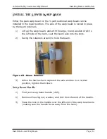
Page 119: ...one of the pulleys attached to the Harness Pulley Support The knot above the handle should be about an inch below the pulley Note If the knot was placed correctly the pickers should still return to the end of the picker rod at each end of the beater and the cord should stop before the knot stops the cord from moving any farther 2 Take it under the pulley on the back face of the beater upright unde...

Page 120: ...f cord left beyond the knot you may want to snip off the excess cord 6 Repeat these steps for the other side of the loom TWO BOX FLYSHUTTLE DROPBOX MOVEMENT Attach the shift handle The shift handle allows you to switch between boxes 1 On each side there is a cable attached to the drop box which has an eyebolt on the end This cable is routed over the top of the drop box pulley and the eyebolt threa...

Page 121: ...e 2 Adjust the bottom screw so that when the boxes are all the way down the upper box is in precise alignment with the shuttle race Figure 115 Flyshuttle adjustment screw Note This adjustment is critical Please make it carefully It is wise to lay a straight edge across the shuttle race and drop box when doing this to assist you in getting the two perfectly aligned 3 When you have it properly adjus...

Page 122: ...nner ATTENTION When shifting the leading end of the handle must be raised first If the trailing end of the handle is lifted first the handle will lock up and not shift Also you want to make sure that the turnbuckles are not adjusted so tightly as to not allow the boxes to drop to their full down position Once properly adjusted tighten the lock nut of each turnbuckle to keep them from moving FOUR B...

Page 123: ...ble 1 To give yourself some slack in the cable it may be helpful to raise the drop box on the side you are working on to its uppermost position 2 To hold it in this position you can insert one of your shuttles halfway into the box that is now aligned with the shuttle race Attach the cable 1 Unwrap the cable that is attached to the top of each drop box 2 Run each cable over to the shift handle Figu...

Page 124: ... other side of the loom 6 Once both cables are attached you will need to adjust the cable lengths Note When you slide the shift handle back and forth notice that there are four detents or places where the shift handle can be stopped Each of these four detents corresponds to the four shuttle boxes 7 The best way to adjust these cables is to slide the shift handle to either the far left or far right...

Page 125: ...o perfectly aligned 10 When you have it properly adjusted secure the lock nuts 11 Once you have adjusted both cables it s a good idea to put the shift handle in each detent position and check the boxes on each side for alignment Note It is possible that there will be some slight variation in the spacing of the drop box shelves so you may not get absolutely perfect alignment If this is the case for...

Page 126: ......

Page 127: ...A Series Dobby Loom Assembly Manual Finish Setting Up Your Loom Finish Setting Up Your Loom Page 119 FINISH SETTING UP YOUR LOOM FINISH SETTING UP YOUR LOOM ...

Page 128: ...Make sure the tips are oriented in the same direction before placing the Compu Dobby on the loom Figure 119 Solenoid Concave Tips 1 Take the Compu Dobby solenoid box and thumbscrews to the loom 2 Slide the Compu Dobby box over the dobby head rest it on the support pins and hold it in place while you line the side holes of the box up to the holes in the dobby backboard Figure 120 Compu Dobby Instal...

Page 129: ...m insert Remember one cable for each slot one solenoid for each cable Surge Protectors and UPS Surge protectors are electronic protection devices that limit the amount of electrical current that can be delivered to your equipment UPS Uninterruptable Power Supply offer short term backup power in the event of a black or brown out Though your power supply is regulated by your utility company occasion...

Page 130: ... executed separately from the WeavePoint installation Other loom control software may require that you download the driver from the AVL website http www avlusa com resources library Driver installation on Windows systems can take up to 45 minutes to associate the USB driver with the loom This is especially true for PCs with slower processors and older operating systems For the first time communica...

Page 131: ...he dobby arm so that it touches the rubber bumper in the top of the slot in the right side of the dobby head 3 Look inside your dobby head so that you can see the dobby arm straight on and position yourself directly in front of cable number 1 4 While continuing to hold the dobby arm up against the bumper with your right hand tap the other end of the dobby arm with your left hand and sight down the...

Page 132: ...osition Note Viewing is achieved through the side windows on the Compu Dobby However you may want to remove the Compu Dobby from the loom in order to more clearly see the slide plate positioning 3 Rotate the E Lift motor pulley clockwise to take the slack out of the cable Ensure the cable does not overlap onto itself 4 Continue rotating the pulley while observing the slide plate Make sure the foll...

Page 133: ...e jam nut to lock in this turnbuckle position Mode Selection The E Lift is programmed with two modes double or single shed selection At power on the E Lift begins in the Double Shed mode Double Shed ends every lifting cycle with the shed open with one tap of the foot or hand switch For example you ve just completed a pick and the shed is still open You depress the foot switch which initiates the s...

Page 134: ...ged idleness Inspect the cables for wear especially where they move over a pulley Do this monthly when in regular use and immediately before use upon prolonged idleness ASSEMBLING THE BENCH The bench comes disassembled to facilitate shipping The contents of the box are one bench top with two metal brackets attached two legs two feet one lower crosspiece one hardware package instructions 1 Attach t...

Page 135: ... best for your height Figure 121 Bench Note The angle of the bench top is adjustable Set it to the amount of tilt that you prefer and tighten the two nuts and bolts that attach the brackets to the legs There are two holes on one edge of the bench top which can be used to mount the AVL bench bag This bag which can be ordered separately from AVL gives you a handy place to store shuttles bobbins and ...

Page 136: ......

Page 137: ...A Series Dobby Loom Assembly Manual Appendix I Optional Equipment Appendix I Optional Equipment Page 129 APPENDIX I OPTIONAL EQUIPMENT APPENDIX I OPTIONAL EQUIPMENT ...

Page 138: ... sure that the removable portion of the raddle is to the top Once mounted into the holes the raddle is not only held firmly in place but is also perfectly centered and can be left in place while weaving Figure 122 Raddle Position TENSION BOX Find your tension box track hardware and tension box Installing Tension Box Mounting Studs 1 In your tension box hardware bag find four 5 16 x2 1 2 carriage b...

Page 139: ...on Box Mounting Assembly 3 Slip the washer and nut on the inside of the loom frame and tighten with a 1 2 socket wrench 4 Repeat this process with the remaining bolts Attaching the track to the track arms 1 Place the track so that the lengthwise groove is on top 2 Mount the track to the brackets on the track arms using two 5 16 x 2 1 2 hex bolts washers and square nuts on each side Figure 124 Atta...

Page 140: ...e the track arms between the two externally mounted studs that you attached to each rear vertical of the loom 2 The track arms should initially go in at an angle with the front stud fit into the notch on the upper edge of the track arm Figure 125 Inserting Track Mount 3 Then lower the track arm assembly to a horizontal position at which point the lower notch on the track arm should align with the ...

Page 141: ...ecting Rod Overhead Beater Tilt Arm Bracket with Connecting Rod Bottom Swing Hardware one hex bolt 3 8 x 2 1 4 two washers and a nut one hex bolt 3 8 x 2 two washers and a nut Overhead Beater Hardware two hex bolts 3 8 x 1 3 4 two washers and a hex nut on each Assembly Note These instructions assume that you are installing the Auto Advance you received with your new loom If you are upgrading your ...

Page 142: ...the spacer onto the auto advance on the inside of the loom 7 Using your 7 16 wrench slightly loosen the bolt that secures the metal triangular bracket to the wood cloth support Adjust the gears 1 Insert a strip of paper between the gears and roll the cloth beam towards you to roll the paper between the gears The paper provides a small amount of space between the gears so that they don t bind durin...

Page 143: ...op Bracket hole then put on the second washer and secure with the nut 4 Repeat this process with the shorter hex bolt 3 8 x 2 and the bottom hole on the Bracket For Overhead Beaters Attach the Tilt Arm Bracket to the Tilt Arm 1 There should be eight holes already drilled into the Tilt Arm 2 Holding the Bracket with the Side Adjustment opening to your right line up the bottom hole with the first ho...

Page 144: ...m 2 Put the washer on the bolt and put bolt through the slot on the Arm and Rod end Put the spacer on and screw the knob back on Figure 129 Auto Advance on loom LOCKING BRAKE The locking brake can be used in place of the tension arm to provide warp tension To release the tension on the warp and advance you must press the brake pedal Depending on the side you want the locking brake on or if you wil...

Page 145: ...he pedal follow these steps to attach it a Remove the Nylock and slide the Bolt out until the end is visible in the vertical hole at the rear of the pedal b Thread three loops of the Tension Tie Up from above the Pedal onto the Bolt followed by one end of the Spring from below the Pedal c Reinsert the Bolt and secure with the Nylock 2 Orient the wood Pedal Assembly inside the loom along the Horizo...

Page 146: ...ck that the bolt is oriented vertically and tighten securely in place Install the mounting bolt for the locking brake Note For Bottom Swing Beaters you must first remove the rear Hex Bolt from the Beater Support Beater Support Spacer along with the two Washers Hex Nut and Pedal Spacer You will then replace it with the bolt in step 1 below 1 Insert the new 5 16 18 x 6 5 8 Bolt with one washer throu...

Page 147: ... Bolt from the inside of the loom through the existing hole previously used by either Tension Arm located in the Rear Vertical Beam of the Side Frame above the Brake Drum 3 Secure the J Bolt with nut to the Side Frame by replacing the Washer and Nylock on the outside of the loom and tighten in place Completing the tie up Note The tie up for the locking brake is completed in the same way whether yo...

Page 148: ...32 Locking brake tieup Installation of the Locking Brake Kit is now complete Adjust brake tension by squeezing the Mini Toggle Lock Tighten tension by pulling on the two ends of the Cord and adjusting the loops by squeezing the Toggle Release tension by moving squeezing and moving the Toggle up and down on the cord allowing the length of the Cord to feed out Releasing the Mini Toggle will retain t...

Page 149: ...cond beam 2 Attach the long piece to the shorter piece using a bolt through the pre drilled hole near the slot for the warp beam Insert a nut through the nut access hole and tighten 3 Position the assembly with the shorter piece over the location for the second beam on the frame The nut access hole on the leg should face to the inside of the loom Figure 133 Bustle Assembly on loom 4 Insert two bol...

Page 150: ...Appendix I Optional Equipment A Series Dobby Loom Assembly Manual Page 142 Bustle 5 Place the warp beam in the slots and add the tension device Figure 134 Bustle with tie up ...

Page 151: ...s Dobby Loom Assembly Manual Appendix II Air Assist Options Appendix II Air Assist Options Page 143 APPENDIX II AIR ASSIST OPTIONS APPENDIX II AIR ASSIST OPTIONS Note These options are not available in Europe ...

Page 152: ...huttle is done by compressed air This air comes into the system via the compressor is forced through the cylinder and is then vented from the system An exhaust valve is the door through which the air leaves FRL This is a filter and regulator together in a single device The air that comes from your compressor feeds directly into the FRL where it s conditioned and its pressure regulated Piloted Valv...

Page 153: ...like 50 duty cycle When using a 50 duty cycle doubling the usage rate is the first step then adding another 50 will insure the compressor is not working at maximum capacity making it last longer and delivering reliable compressed air to AVL products Note If you will be using multiple air components make sure your air compressor is sized to handle all of them Exceptions to the above sizing methods ...

Page 154: ...ir components on your loom Depending on the configuration of your loom the FRL may differ from what is shown here 1 Install the Filter Regulator Lubricator FRL in the pre drilled holes using the screws provided onto the left rear side support 2 Install the air component s for your loom according to the directions in this appendix 3 Connect the FRL to the correct color coded air line from the coil ...

Page 155: ...tem to work you will need to have compressed air available at the loom The A Lift will consume approximately 1 25 CFM Cubic Feet per Minute of air at 100 PSI pounds per square inch when weaving a maximum speed We recommend a compressor rated at double this consumption with a minimum 5 gallon tank This system has been designed to operate from a line pressure between 60 PSI and 100 PSI The pressure ...

Page 156: ...Flow Control Valves pedal under sitting on the Foot Pedal correct color coded air lines A You should have already assembled Lift cylinder and mounting plate pre assembled onto the loom frame If not do so now Air Flow Control Valves the loom bench color coded air lines A Series Dobby Loom Assembly Manual You should have already assembled the 12 Treadle Pulley Lift cylinder and mounting plate pre as...

Page 157: ...with a quicklink in the eyebolt on the upper back right corner of the slide plate The cable goes over a small white plastic pulley with a retainer above it Figure 138 A Lift Return Cable 1 The cable will go down the right side of the dobby back Guide the cable around the bottom of the return pulley on the cam pulley axle then into the center of the loom Figure 139 Position the Pulley ...
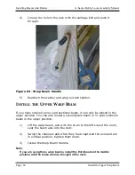
Page 158: ...o remove the spring and replace it once the cable has been anchored on the J bolt 4 Position the pulley on the axle so that the line of the cable from the dobby to the pulley to the spring lever is straight The cable should not be at a diagonal 5 Secure the pulley in place by tightening a stop collar on either side of the pulley Return Spring Adjustment If the slide plate does not move up to the u...

Page 159: ...Guide the lift cable attached to the bottom center of the slide plate down to the left pulley on the axle Figure 141 Slide Plate Eyebolt and cable 2 Clip the end of the cable to the rod end of the cylinder 3 The line of the cable from the dobby to the pulley should be straight The cable should not be at a diagonal from any point to point 4 Slide the pulley into position on the axle and secure it i...

Page 160: ...ched to them Make sure the bracket is facing out from the loom when installing the uprights You will not need to follow the tie up instructions Assemble the Picker Cylinder and Picker Stick The Picker Stick Assembly consists of the picker stick attached to a wooden piece with nut access holes on the opposite end from the picker stick 1 The Picker Stick is attached to the green picker on your flysh...

Page 161: ... Air Shuttle Page 153 4 Place one end of the picker cylinder on the bracket on the upright Place the pin through the bracket and the picker cylinder and secure it with a clevis pin 5 Bolt the other end of the picker cylinder to the end of the picker stick Figure 143 Picker Cylinder ...

Page 162: ...ng places A Unpack the box of components and tubing Locate and layout the components and tubing inside the loom in their general locations Air Tubing Diagram downs and secure them to the loom with 6 x Mount the Left and Right Piloted Valves Piloted Valves will be secured to the inside of the left and right Bottom Horizontals They are already affixed to their mounting brackets If you followed the p...

Page 163: ... pan head sheet metal screws from the hardware pack and use them to mount the left Piloted Valve in the holes on the left bottom horizontal 2 Repeat for the right valve Figure 145 Piloted Valve right 3 Matching the color coding tape connect the plastic tubing from the Piloted Valve to the picker stick cylinder on each side ...

Page 164: ...e Safety Valve will prevent your shuttle from firing unless the Beater is in its rearmost position It is activated by contest with the Beater and must be correctly installed and adjusted if it is to work properly It will mount on the right top horizontal or to the right lower cloth beam support There should be a small metal plate clipped to your valve assembly This is a striker plate It provides w...

Page 165: ...valve arm should strike the plate at about its center Mark and drill two holes with your 9 64 bit and mount the plate using two 8 x 3 4 flat head screws from the hardware pack Adjust the Safety Valve Important You will still need to adjust the position of the safety valve relative to the beater This adjustment is essential to safe operation 1 Use your 5 32 allen wrench to loosen the two allen scre...

Page 166: ...beater in both positions Note DO NOT USE YOUR SYSTEM UNLESS THIS DEVICE IS IN PLACE AND OPERATING Binder Clip Tensioning The wooden binder blocks in the sides of your drop boxes act to brake your shuttle and keep it properly positioned These blocks are kept under tension by thin strips of spring steel two per block If the binders are properly ad justed the shuttle will come into the box and will n...

Page 167: ...f the clips 4 Again check the action of your shuttle against the newly tensioned block Continue to adjust as necessary Calibrating In addition to the few mechanical adjustments you just made you ll need to make some settings at your FRL and at both your Piloted Valves The regulator on the FRL controls the air pressure in the system The Piloted Valves control the action of the pickers and allow you...

Page 168: ...e you set the speed of your shuttles 1 Pull the yellow locking ring up and turn the knob As with all these settings you ll need to play around a bit until you ve tuned the system to your particular need We recommend that you begin with a pressure setting of 40 p s i If the shuttle doesn t make it completely across the race increase the pressure or loosen the binder clips If it bounces out of the b...

Page 169: ...eater Follow the instructions in the section for the Overhead Beater Assembly starting on page 94 to install the beater The axle and axle blocks will be an assembly composed of plastic blocks with a metal rod with some additional component It will install in the same way as the normal axle block although you may need some additional assistance when attaching it Mount the Beater Air Cylinder The Ai...

Page 170: ...al to the Beater Air Cylinder CONNECTING THE COMPONENTS TO COMPRESSED AIR Your loom is now ready to be hooked up to a compressed air line This line will be connected to the FRL unit You need to purchase a fitting to hook up to your air line For convenience we suggest that you use a quick disconnect type fitting which can easily be released from the loom without any tools You will need to buy a mal...

Page 171: ...ent you change weaving patterns as you w needed when you are lifting more harnesses activated by depressing the foot valve The harnesses lift your weaving speed can adjusting the flow co valve adjusts inward and the right valve adjusts outward of FRL Detail may vary YSTEM Check the FRL weekly if you use your loom daily Drain the filter bowl if you note a build up of condensation a drain plug at th...

Page 172: ... A Series Dobby Loom Assembly Manual Page 164 Maintaining Your System 6 Check and tighten the bolts as needed 7 Adjust the various mechanisms as needed NOTE Please disconnect the air from your compressor before you drain your system ...

Page 173: ...A Series Dobby Loom Assembly Manual The Fine Print The Fine Print Page 165 THE FINE PRINT THE FINE PRINT ...

Page 174: ...ip it to you Your Compu Dobby is fully warranted for two years If a part wears or breaks during this period we will replace or repair it at our discretion but at no charge to you AVL Returns Policy All goods excepting software may be returned for refund within thirty 30 days of the shipping date A 15 restocking fee will be assessed for all but defective items AVL will pay all shipping costs for de...

Page 175: ...ating to electromagnetic compatibility safety of electrical equipment designed for use within certain voltage limits radio equipment and telecommunications terminal equipment and on the ecodesign of energy related products Compliance is indicated by the CE marking The manufacturer of this product is AVL Looms Inc 2360 Park Avenue Chico CA 95928 USA A declaration of conformity to the requirements o...

Page 176: ...The Fine Print A Series Dobby Loom Assembly Manual Page 168 Notice to Users in the European Union ...

Reviews: