Frame Assembly
Page | 28
2)
Figure
Note:
The motor box is quite heavy, so if you have a couple of pieces of 2” x 4” to
slip under the motor box, this will
bolts and blocks in place.
3)
4)
Frame Assembly
28
Make sure
and the round foot switch connector faces the front of the loom.
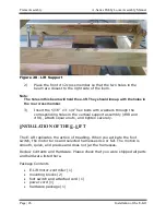
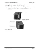
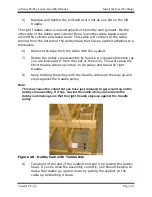
Figure 30 - E-lift attached to supports
The motor box is quite heavy, so if you have a couple of pieces of 2” x 4” to
slip under the motor box, this will
bolts and blocks in place.
From the top of the cross member, p
bolt and flat washer
with the exposed ends pointing to the floor.
Thread a mounting block onto each set of bolts and then engage
the bolts in the corresponding holes in the E
Make sure that the E
and the round foot switch connector faces the front of the loom.
lift attached to supports
The motor box is quite heavy, so if you have a couple of pieces of 2” x 4” to
slip under the motor box, this will
bolts and blocks in place.
From the top of the cross member, p
bolt and flat washer
with the exposed ends pointing to the floor.
Thread a mounting block onto each set of bolts and then engage
the bolts in the corresponding holes in the E
that the E-Lift power switch faces to the rear of the l
and the round foot switch connector faces the front of the loom.
lift attached to supports
The motor box is quite heavy, so if you have a couple of pieces of 2” x 4” to
slip under the motor box, this will help elevate it into position while getting the
bolts and blocks in place.
From the top of the cross member, p
bolt and flat washer into each of the four holes and let them hang
with the exposed ends pointing to the floor.
Thread a mounting block onto each set of bolts and then engage
the bolts in the corresponding holes in the E
A
Lift power switch faces to the rear of the l
and the round foot switch connector faces the front of the loom.
lift attached to supports
The motor box is quite heavy, so if you have a couple of pieces of 2” x 4” to
help elevate it into position while getting the
From the top of the cross member, p
into each of the four holes and let them hang
with the exposed ends pointing to the floor.
Thread a mounting block onto each set of bolts and then engage
the bolts in the corresponding holes in the E
A-Series Dobby Loom Assembly Manual
Lift power switch faces to the rear of the l
and the round foot switch connector faces the front of the loom.
The motor box is quite heavy, so if you have a couple of pieces of 2” x 4” to
help elevate it into position while getting the
From the top of the cross member, place one 5/16” x 6 1/2” hex
into each of the four holes and let them hang
with the exposed ends pointing to the floor.
Thread a mounting block onto each set of bolts and then engage
the bolts in the corresponding holes in the E-Lift mounting plate.
Series Dobby Loom Assembly Manual
Installation of the E
Lift power switch faces to the rear of the l
and the round foot switch connector faces the front of the loom.
The motor box is quite heavy, so if you have a couple of pieces of 2” x 4” to
help elevate it into position while getting the
lace one 5/16” x 6 1/2” hex
into each of the four holes and let them hang
Thread a mounting block onto each set of bolts and then engage
Lift mounting plate.
Series Dobby Loom Assembly Manual
allation of the E
Lift power switch faces to the rear of the loom
and the round foot switch connector faces the front of the loom.
The motor box is quite heavy, so if you have a couple of pieces of 2” x 4” to
help elevate it into position while getting the
lace one 5/16” x 6 1/2” hex
into each of the four holes and let them hang
Thread a mounting block onto each set of bolts and then engage
Lift mounting plate.
Series Dobby Loom Assembly Manual
allation of the E-Lift
oom
The motor box is quite heavy, so if you have a couple of pieces of 2” x 4” to
help elevate it into position while getting the
lace one 5/16” x 6 1/2” hex
into each of the four holes and let them hang
Thread a mounting block onto each set of bolts and then engage
Lift mounting plate.

