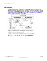
The reverse-wiring compensation feature operates as follows. If an apparent disconnect takes
place immediately after the first ringing signal, the software time stamps the event and
temporarily remove the call from the console loop key.
If another such ringing/disconnect event occurs during the No Ringing Detector (NRD) time,
the trunk is considered "possibly reverse-wired" and a threshold counter starts. Calls on trunks
identified as possibly reverse-wired are presented to the attendant during the initial ring,
removed, and then continuously presented after the second ring. If a call on a possibly reverse-
wired trunk is abandoned before the attendant answers, it is disconnected after the NRD timer
expires.
A trunk identified as possibly reverse-wired is switched by the software to loop start processing
after the second ring. This switching takes place on a call-by-call basis. So if a previously
correctly wired trunk becomes reverse-wired, the next incoming call is marked as possibly
reverse-wired and the threshold count begins.
If the threshold count exceeds its limit, an error message is printed and the trunk is registered
as "positively reverse wired." Once identified as positively reverse wired, the call is presented
continuously from the first ring. When a reverse-wired trunk becomes correctly wired, the first
subsequent call clears the threshold counter and normal ground start processing is
implemented.
Note:
The far-end can reverse battery and ground upon receipt of attendant answer.
Note:
The near-end provides a high-impedance (>150k ohms) disconnect signal of at least 50 ms
before reconnecting the ground detector.
Outgoing calls
For outgoing calls, the trunk provides a ground to the ring lead. The CO responds by grounding
the tip and returning dial tone. After the tip ground is detected by the card, a low-resistance
path is placed between the tip and ring leads and the ground is removed from the ring.
Addressing is then applied from the system in the form of loop (interrupting) dial pulses or
DTMF tones. See
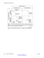
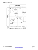
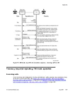
Figure 111: Ground start call states - outgoing call to CO/FX/WATS
on
page 393 and
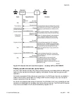
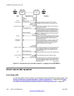
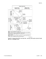
Figure 112: Ground start call connection sequence - outgoing call to CO/FX/
on page 394.
The Polarity-Sensitive/Polarity-Insensitive Packs (PSP and PIP) feature must be set to provide
for proper outgoing call-duration recording with ground start operation. Refer to the description
of loop start operation in this section for a more complete discussion of PSP and PIP.
NT8D14 Universal Trunk card
392 Circuit Card Reference
July 2011
Summary of Contents for 1000 Series
Page 1: ...Circuit Card Reference Nortel Communication Server 1000 7 0 NN43001 311 04 04 July 2011 ...
Page 20: ...20 Circuit Card Reference July 2011 ...
Page 30: ...Introduction 30 Circuit Card Reference July 2011 Comments infodev avaya com ...
Page 116: ...Option settings 116 Circuit Card Reference July 2011 Comments infodev avaya com ...
Page 143: ...Figure 25 CP PIV card front Physical description Circuit Card Reference July 2011 143 ...
Page 148: ...NT4N39AA CP Pentium IV Card 148 Circuit Card Reference July 2011 Comments infodev avaya com ...
Page 287: ...Figure 86 Clock Controller Option 3 Operation Circuit Card Reference July 2011 287 ...
Page 302: ...NT5K21 XMFC MFE card 302 Circuit Card Reference July 2011 Comments infodev avaya com ...
Page 346: ...NT6D80 MSDL card 346 Circuit Card Reference July 2011 Comments infodev avaya com ...
Page 353: ...Figure 96 NTDK16 DLC Functional description Circuit Card Reference July 2011 353 ...
Page 461: ...Figure 147 Paging trunk operation Applications Circuit Card Reference July 2011 461 ...
Page 462: ...NT8D15 E and M Trunk card 462 Circuit Card Reference July 2011 Comments infodev avaya com ...
Page 500: ...NTAK09 1 5 Mb DTI PRI card 500 Circuit Card Reference July 2011 Comments infodev avaya com ...
Page 512: ...NTAK10 2 0 Mb DTI card 512 Circuit Card Reference July 2011 Comments infodev avaya com ...
Page 534: ...NTAK79 2 0 Mb PRI card 534 Circuit Card Reference July 2011 Comments infodev avaya com ...
Page 550: ...NTBK22 MISP card 550 Circuit Card Reference July 2011 Comments infodev avaya com ...
Page 560: ...NTBK50 2 0 Mb PRI card 560 Circuit Card Reference July 2011 Comments infodev avaya com ...
Page 595: ...Figure 165 MGC block diagram Introduction Circuit Card Reference July 2011 595 ...
Page 662: ...NTRB21 DTI PRI DCH TMDI card 662 Circuit Card Reference July 2011 Comments infodev avaya com ...
Page 668: ...NTVQ01xx Media Card 668 Circuit Card Reference July 2011 Comments infodev avaya com ...
Page 700: ......


