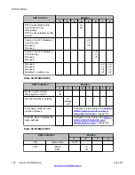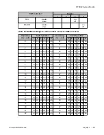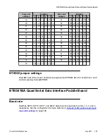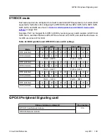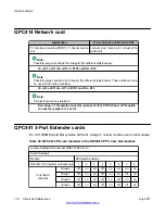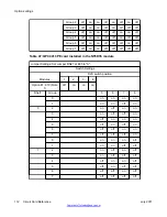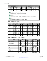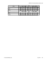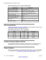
The NT1R20 OPS analog line card provides:
• line supervision
• hookflash
• battery reversal
Each unit is independently configured by software control in the Analog (500/2500 type)
Telephone Administration program LD 10.
You can install this card in any IPE slot.
A maximum of four analog line cards can be installed in each Media Gateway and Media
Gateway Expansion.
The NT1R20 OPS Analog Line Card can be installed in slots 1, 2, 3, and 4 of the Media
Gateway and slots 7, 8, 9, and 10 of the Media Gateway Expansion.
Physical description
The OPS card measures 31.75 by 25.40 cm (12.5 by 10 in.) It connects to the IPE backplane
through a 160-pin connector shroud. A 25-pair amphenol connector below the card is cabled
to the cross connect terminal. Telephone lines from station equipment cross connect to the
OPS analog line card at the cross connect using a wiring plan similar to trunk cards. See
Communication Server 1000M and Meridian 1 Large System Installation and Configuration
(NN43021-310) for cross connect terminations.
The OPS analog line card mounts in any IPE slot.
Self Test
The faceplate of the NT1R20 OPS analog line card is equipped with a red LED. When an OPS
analog line card is installed, the LED remains lit for two to five seconds while the self-test runs.
If the self-test is completed successfully, the LED flashes three times and remains lit. When
the card is configured and enabled in software; then the LED goes out. If the LED continues
to flash or remains weakly lit, replace the card. See
Figure 20: OPS analog line card -
on page 119.
NT1R20 Off-Premise Station Analog Line card
118 Circuit Card Reference
July 2011
Summary of Contents for 1000 Series
Page 1: ...Circuit Card Reference Nortel Communication Server 1000 7 0 NN43001 311 04 04 July 2011 ...
Page 20: ...20 Circuit Card Reference July 2011 ...
Page 30: ...Introduction 30 Circuit Card Reference July 2011 Comments infodev avaya com ...
Page 116: ...Option settings 116 Circuit Card Reference July 2011 Comments infodev avaya com ...
Page 143: ...Figure 25 CP PIV card front Physical description Circuit Card Reference July 2011 143 ...
Page 148: ...NT4N39AA CP Pentium IV Card 148 Circuit Card Reference July 2011 Comments infodev avaya com ...
Page 287: ...Figure 86 Clock Controller Option 3 Operation Circuit Card Reference July 2011 287 ...
Page 302: ...NT5K21 XMFC MFE card 302 Circuit Card Reference July 2011 Comments infodev avaya com ...
Page 346: ...NT6D80 MSDL card 346 Circuit Card Reference July 2011 Comments infodev avaya com ...
Page 353: ...Figure 96 NTDK16 DLC Functional description Circuit Card Reference July 2011 353 ...
Page 461: ...Figure 147 Paging trunk operation Applications Circuit Card Reference July 2011 461 ...
Page 462: ...NT8D15 E and M Trunk card 462 Circuit Card Reference July 2011 Comments infodev avaya com ...
Page 500: ...NTAK09 1 5 Mb DTI PRI card 500 Circuit Card Reference July 2011 Comments infodev avaya com ...
Page 512: ...NTAK10 2 0 Mb DTI card 512 Circuit Card Reference July 2011 Comments infodev avaya com ...
Page 534: ...NTAK79 2 0 Mb PRI card 534 Circuit Card Reference July 2011 Comments infodev avaya com ...
Page 550: ...NTBK22 MISP card 550 Circuit Card Reference July 2011 Comments infodev avaya com ...
Page 560: ...NTBK50 2 0 Mb PRI card 560 Circuit Card Reference July 2011 Comments infodev avaya com ...
Page 595: ...Figure 165 MGC block diagram Introduction Circuit Card Reference July 2011 595 ...
Page 662: ...NTRB21 DTI PRI DCH TMDI card 662 Circuit Card Reference July 2011 Comments infodev avaya com ...
Page 668: ...NTVQ01xx Media Card 668 Circuit Card Reference July 2011 Comments infodev avaya com ...
Page 700: ......

