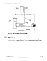
This card occupies two card slots in the main or expansion cabinets. The Lineside T1 card can
be installed in the system's main cabinet or one of the expansion cabinets (there are no
limitations on the number of cards that can be installed in the Cabinet system).
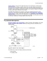
The Lineside T1 card emulates an analog line card to the system software; therefore, each
channel is independently configurable by software control in LD 10. The Lineside T1 card also
comes equipped with a Man-Machine Interface (MMI) maintenance program. This feature
provides diagnostic information regarding the status of the T1 link.
The NT5D11 Lineside T1 interface card is an IPE line card that can be installed in the NT8D37
IPE module. Up to eight cards can be installed.
Physical description
The Lineside T1 card mounts into any two consecutive IPE slots. The card consists of a
motherboard and a daughterboard. The motherboard circuitry is contained on a standard 31.75
by 25.40 cm. (12.5 by 10.0 in) printed circuit board. The daughterboard is contained on a 5.08
by 15.24 cm (2.0 by 6.0 in) printed circuit board and mounts to the motherboard on six
standoffs.
Card connections
The Lineside T1 card uses the NT8D81AA Tip and Ring cable to connect from the IPE
backplane to the 25-pair amphenol connector on the IPE I/O input/output (I/O) panel. The I/O
panel connector then connects directly to a T1 line, external alarm, and an MMI terminal or
modem using the NT5D13AA Lineside T1 I/O cable available from Nortel.
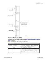
Faceplate
The faceplate of the card is twice as wide as the other standard analog and digital line cards,
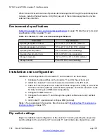
and occupies two card slots. It comes equipped with four LED indicators. See
on page 151.
NT5D11 and NT5D14 Lineside T1 Interface cards
150 Circuit Card Reference
July 2011
Summary of Contents for 1000 Series
Page 1: ...Circuit Card Reference Nortel Communication Server 1000 7 0 NN43001 311 04 04 July 2011 ...
Page 20: ...20 Circuit Card Reference July 2011 ...
Page 30: ...Introduction 30 Circuit Card Reference July 2011 Comments infodev avaya com ...
Page 116: ...Option settings 116 Circuit Card Reference July 2011 Comments infodev avaya com ...
Page 143: ...Figure 25 CP PIV card front Physical description Circuit Card Reference July 2011 143 ...
Page 148: ...NT4N39AA CP Pentium IV Card 148 Circuit Card Reference July 2011 Comments infodev avaya com ...
Page 287: ...Figure 86 Clock Controller Option 3 Operation Circuit Card Reference July 2011 287 ...
Page 302: ...NT5K21 XMFC MFE card 302 Circuit Card Reference July 2011 Comments infodev avaya com ...
Page 346: ...NT6D80 MSDL card 346 Circuit Card Reference July 2011 Comments infodev avaya com ...
Page 353: ...Figure 96 NTDK16 DLC Functional description Circuit Card Reference July 2011 353 ...
Page 461: ...Figure 147 Paging trunk operation Applications Circuit Card Reference July 2011 461 ...
Page 462: ...NT8D15 E and M Trunk card 462 Circuit Card Reference July 2011 Comments infodev avaya com ...
Page 500: ...NTAK09 1 5 Mb DTI PRI card 500 Circuit Card Reference July 2011 Comments infodev avaya com ...
Page 512: ...NTAK10 2 0 Mb DTI card 512 Circuit Card Reference July 2011 Comments infodev avaya com ...
Page 534: ...NTAK79 2 0 Mb PRI card 534 Circuit Card Reference July 2011 Comments infodev avaya com ...
Page 550: ...NTBK22 MISP card 550 Circuit Card Reference July 2011 Comments infodev avaya com ...
Page 560: ...NTBK50 2 0 Mb PRI card 560 Circuit Card Reference July 2011 Comments infodev avaya com ...
Page 595: ...Figure 165 MGC block diagram Introduction Circuit Card Reference July 2011 595 ...
Page 662: ...NTRB21 DTI PRI DCH TMDI card 662 Circuit Card Reference July 2011 Comments infodev avaya com ...
Page 668: ...NTVQ01xx Media Card 668 Circuit Card Reference July 2011 Comments infodev avaya com ...
Page 700: ......

