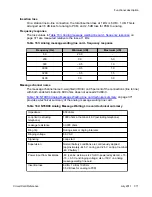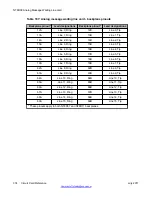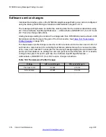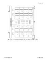
Power for lighting the message waiting lights is provided by either the peripheral equipment
power supply or the ringing generator. Logic on the message waiting line card interrupts the –
150 V DC signal at 1 Hz intervals to provide a flashing message waiting light.
Technical summary or electrical specifications
Analog line interface
The NT8D09 Analog Message Waiting Line Card meets the EIA/TA464 standard for ONS Type
II line cards.
Table 162: Analog message waiting line card - line interface unit electrical
on page 370 shows a summary of the analog line interface unit electrical
characteristics.
Table 162: Analog message waiting line card - line interface unit electrical
characteristics
Characteristics
Description
Impedance
600 ohms
Loop limit (excluding
telephone)
1000 ohms at nominal –48 V (excluding telephone)
Leakage resistance
30,000 ohms
Ring trip
During silent or ringing intervals
Ringing voltage
86 V ac
Signaling
Loop start
Supervision
Normal battery conditions are continuously applied
(approximately –44.5 V on ring and –2.5 V on tip at nominal
–48 V battery)
Power input from backplane
–48 (can be as low as –42 for DC-powered systems), +15,
+8.5, –150 V and ringing voltage
Insertion loss
4 dB ±1 dB at 1020 Hz
3.5 dB loss for analog to PCM
0.5 dB loss for PCM to analog
Input impedance
The impedance at tip and ring is 600 ohms with a return loss of:
• 20 dB for 200-500 Hz
• 26 dB for 500-3400 Hz
NT8D09 Analog Message Waiting Line card
370 Circuit Card Reference
July 2011
Summary of Contents for 1000 Series
Page 1: ...Circuit Card Reference Nortel Communication Server 1000 7 0 NN43001 311 04 04 July 2011 ...
Page 20: ...20 Circuit Card Reference July 2011 ...
Page 30: ...Introduction 30 Circuit Card Reference July 2011 Comments infodev avaya com ...
Page 116: ...Option settings 116 Circuit Card Reference July 2011 Comments infodev avaya com ...
Page 143: ...Figure 25 CP PIV card front Physical description Circuit Card Reference July 2011 143 ...
Page 148: ...NT4N39AA CP Pentium IV Card 148 Circuit Card Reference July 2011 Comments infodev avaya com ...
Page 287: ...Figure 86 Clock Controller Option 3 Operation Circuit Card Reference July 2011 287 ...
Page 302: ...NT5K21 XMFC MFE card 302 Circuit Card Reference July 2011 Comments infodev avaya com ...
Page 346: ...NT6D80 MSDL card 346 Circuit Card Reference July 2011 Comments infodev avaya com ...
Page 353: ...Figure 96 NTDK16 DLC Functional description Circuit Card Reference July 2011 353 ...
Page 461: ...Figure 147 Paging trunk operation Applications Circuit Card Reference July 2011 461 ...
Page 462: ...NT8D15 E and M Trunk card 462 Circuit Card Reference July 2011 Comments infodev avaya com ...
Page 500: ...NTAK09 1 5 Mb DTI PRI card 500 Circuit Card Reference July 2011 Comments infodev avaya com ...
Page 512: ...NTAK10 2 0 Mb DTI card 512 Circuit Card Reference July 2011 Comments infodev avaya com ...
Page 534: ...NTAK79 2 0 Mb PRI card 534 Circuit Card Reference July 2011 Comments infodev avaya com ...
Page 550: ...NTBK22 MISP card 550 Circuit Card Reference July 2011 Comments infodev avaya com ...
Page 560: ...NTBK50 2 0 Mb PRI card 560 Circuit Card Reference July 2011 Comments infodev avaya com ...
Page 595: ...Figure 165 MGC block diagram Introduction Circuit Card Reference July 2011 595 ...
Page 662: ...NTRB21 DTI PRI DCH TMDI card 662 Circuit Card Reference July 2011 Comments infodev avaya com ...
Page 668: ...NTVQ01xx Media Card 668 Circuit Card Reference July 2011 Comments infodev avaya com ...
Page 700: ......

