Line interface units
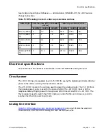
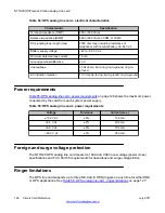
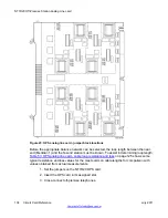
The NT1R20 OPS analog line card contains eight independently configurable interface units.
Relays are provided in each unit to apply ringing onto the line. Signal detection circuits monitor
on-hook/off-hook signaling. Two codecs are provided for performing Analog/Digital (A/D) and
Digital/Analog (D/A) conversion of analog voiceband signals to digital PCM signals.
Each codec supports four interface units and contains switchable pads for control of
transmission loss on a per unit basis. The following features are common to all units on the
card:
• OPS or ONS service configurable on a per unit basis
• terminating impedance (600 or 900 ohms) selectable on a per unit basis
• standard or complex balance impedance (600 or 900 ohms, 3COM1 or 3COM2)
selectable on a per unit basis
• loopback of PCM signals over DS-30X network loop for diagnostic purposes
Signaling and control
This portion of the card provides circuits that establish, supervise, and take down call
connections. These circuits work with the CPU to operate line interface circuits during calls.
The circuits receive outgoing call signaling messages from the CPU and return incoming call
status information over the DS-30X network loop.
Card control functions
Control functions are provided by a microcontroller, a card LAN interface, and signaling and
control circuits on the NT1R20 OPS analog line card.
Microcontroller
The OPS analog line card contains a microcontroller that controls the internal operation of the
card and the serial card LAN link to the controller card. The microcontroller controls the
following:
• reporting to the CE CPU through the card LAN link:
- card identification (card type, vintage, and serial number)
- firmware version
- self-test status
NT1R20 Off-Premise Station Analog Line card
122 Circuit Card Reference
July 2011
Summary of Contents for 1000 Series
Page 1: ...Circuit Card Reference Nortel Communication Server 1000 7 0 NN43001 311 04 04 July 2011 ...
Page 20: ...20 Circuit Card Reference July 2011 ...
Page 30: ...Introduction 30 Circuit Card Reference July 2011 Comments infodev avaya com ...
Page 116: ...Option settings 116 Circuit Card Reference July 2011 Comments infodev avaya com ...
Page 143: ...Figure 25 CP PIV card front Physical description Circuit Card Reference July 2011 143 ...
Page 148: ...NT4N39AA CP Pentium IV Card 148 Circuit Card Reference July 2011 Comments infodev avaya com ...
Page 287: ...Figure 86 Clock Controller Option 3 Operation Circuit Card Reference July 2011 287 ...
Page 302: ...NT5K21 XMFC MFE card 302 Circuit Card Reference July 2011 Comments infodev avaya com ...
Page 346: ...NT6D80 MSDL card 346 Circuit Card Reference July 2011 Comments infodev avaya com ...
Page 353: ...Figure 96 NTDK16 DLC Functional description Circuit Card Reference July 2011 353 ...
Page 461: ...Figure 147 Paging trunk operation Applications Circuit Card Reference July 2011 461 ...
Page 462: ...NT8D15 E and M Trunk card 462 Circuit Card Reference July 2011 Comments infodev avaya com ...
Page 500: ...NTAK09 1 5 Mb DTI PRI card 500 Circuit Card Reference July 2011 Comments infodev avaya com ...
Page 512: ...NTAK10 2 0 Mb DTI card 512 Circuit Card Reference July 2011 Comments infodev avaya com ...
Page 534: ...NTAK79 2 0 Mb PRI card 534 Circuit Card Reference July 2011 Comments infodev avaya com ...
Page 550: ...NTBK22 MISP card 550 Circuit Card Reference July 2011 Comments infodev avaya com ...
Page 560: ...NTBK50 2 0 Mb PRI card 560 Circuit Card Reference July 2011 Comments infodev avaya com ...
Page 595: ...Figure 165 MGC block diagram Introduction Circuit Card Reference July 2011 595 ...
Page 662: ...NTRB21 DTI PRI DCH TMDI card 662 Circuit Card Reference July 2011 Comments infodev avaya com ...
Page 668: ...NTVQ01xx Media Card 668 Circuit Card Reference July 2011 Comments infodev avaya com ...
Page 700: ......


