


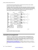


card consists of four baud rate generators, four RS-232-C driver/receiver pairs, and the
jumpers and logic needed to configure the UARTs.
The address select switches and logic on the card always address the UARTs using two pairs
of addresses: 0 and 1, and 2 and 3 through 15 and 16. The pairs do not need to be consecutive.
Other switches on the board determine the baud rate for each individual port and whether the
port is configured to talk to a terminal (DTE equipment) or a modem (DCE equipment).
Instructions for setting the jumpers are given later in this section.
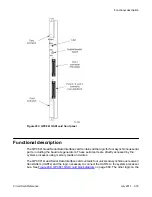
Figure 204: QPC841 QSDI card block diagram
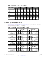
Connector pin assignments
Connector J1 is connected to port one, and uses the RS-232-C standard DB-25-pinout.
Connector J2 is connected to ports two, three, and four, and is a non-standard pinout that
requires an adapter cable. An adapter cable (NT8D96) splits the J2 signals out to three
standard RS-232-C connectors. Port 2 is connected to connector A, Port 3 is connected to
connector B, and Port 4 is connected to connector C.
Table 281: Connector J1 pin assignments
on page 681 shows the pinouts for connector J1,
Table 282: Connector J2 pin assignments
on page 681 shows the pinouts for connector
J2.
QPC841 Quad Serial Data Interface card
680 Circuit Card Reference
July 2011
Summary of Contents for 1000 Series
Page 1: ...Circuit Card Reference Nortel Communication Server 1000 7 0 NN43001 311 04 04 July 2011 ...
Page 20: ...20 Circuit Card Reference July 2011 ...
Page 30: ...Introduction 30 Circuit Card Reference July 2011 Comments infodev avaya com ...
Page 116: ...Option settings 116 Circuit Card Reference July 2011 Comments infodev avaya com ...
Page 143: ...Figure 25 CP PIV card front Physical description Circuit Card Reference July 2011 143 ...
Page 148: ...NT4N39AA CP Pentium IV Card 148 Circuit Card Reference July 2011 Comments infodev avaya com ...
Page 287: ...Figure 86 Clock Controller Option 3 Operation Circuit Card Reference July 2011 287 ...
Page 302: ...NT5K21 XMFC MFE card 302 Circuit Card Reference July 2011 Comments infodev avaya com ...
Page 346: ...NT6D80 MSDL card 346 Circuit Card Reference July 2011 Comments infodev avaya com ...
Page 353: ...Figure 96 NTDK16 DLC Functional description Circuit Card Reference July 2011 353 ...
Page 461: ...Figure 147 Paging trunk operation Applications Circuit Card Reference July 2011 461 ...
Page 462: ...NT8D15 E and M Trunk card 462 Circuit Card Reference July 2011 Comments infodev avaya com ...
Page 500: ...NTAK09 1 5 Mb DTI PRI card 500 Circuit Card Reference July 2011 Comments infodev avaya com ...
Page 512: ...NTAK10 2 0 Mb DTI card 512 Circuit Card Reference July 2011 Comments infodev avaya com ...
Page 534: ...NTAK79 2 0 Mb PRI card 534 Circuit Card Reference July 2011 Comments infodev avaya com ...
Page 550: ...NTBK22 MISP card 550 Circuit Card Reference July 2011 Comments infodev avaya com ...
Page 560: ...NTBK50 2 0 Mb PRI card 560 Circuit Card Reference July 2011 Comments infodev avaya com ...
Page 595: ...Figure 165 MGC block diagram Introduction Circuit Card Reference July 2011 595 ...
Page 662: ...NTRB21 DTI PRI DCH TMDI card 662 Circuit Card Reference July 2011 Comments infodev avaya com ...
Page 668: ...NTVQ01xx Media Card 668 Circuit Card Reference July 2011 Comments infodev avaya com ...
Page 700: ......