Interface (MMI) maintenance program, which provides diagnostic information regarding
the status of the E1 link.
• NT5D33AC/NT5D34AC – Enhanced Lineside E1 Interface (ELEI) cards
The ELEI card is similar to an LEI card, but is enhanced to allow the capability of
transporting caller information using the proprietary signaling interface Channel
Associated Signaling (CAS+).
ELEI cards can operate in one of two modes: LEI mode, or enhanced (ELEI) mode. In
LEI mode, this card is fully compatible with, and provides the same functionality as, the
standard LEI card. In ELEI mode, this card can be connected to any CAS+ compliant
systems. This includes wireless server hosting Digital Enhanced Cordless Telephones
(DECTs), voice response units, voice messaging systems, and trading turret systems
(used in stock market applications). More information regarding CAS+ can be obtained
through Nortel Development Partner program.
Note:
As the ELEI cards provide identical functionality to LEI cards, references to LEI cards
in this chapter also apply to ELEI cards unless specified otherwise.
Install the NT5D33 version of the LEI/ELEI card in the NT8D37 IPE module.
Install the NT5D34 version of the LEI/ELEI card in:
• the NTAK11 Cabinet
• the NTAK12 Expansion Cabinet
• the NT1P70 Small Remote IPE Main Cabinet
• the NTAK12 Small Remote IPE Expansion Cabinet
Physical description
The LEI mounts in two consecutive card slots in the IPE shelf. It uses 16 channels on the first
slot and 14 channels on the second. The LEI includes a motherboard (31.75 by 25.40 cm (12.5
by 10 in) and a daughterboard (5.08 by 15.24 cm (2 by 6 in).
Card connections
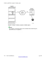
The LEI uses the NT8D81AA Tip and Ring cable to connect from the IPE backplane to the 25-
pair Amphenol connector on the IPE Input/Output (I/O) panel. The I/O panel connector
connects to a E1 line, external alarm and an MMI terminal or modem, using the NT5D35 or
NT5D36 lineside I/O cable available from Nortel.
NT5D33 and NT5D34 Lineside E1 Interface cards
194 Circuit Card Reference
July 2011
Summary of Contents for 1000 Series
Page 1: ...Circuit Card Reference Nortel Communication Server 1000 7 0 NN43001 311 04 04 July 2011 ...
Page 20: ...20 Circuit Card Reference July 2011 ...
Page 30: ...Introduction 30 Circuit Card Reference July 2011 Comments infodev avaya com ...
Page 116: ...Option settings 116 Circuit Card Reference July 2011 Comments infodev avaya com ...
Page 143: ...Figure 25 CP PIV card front Physical description Circuit Card Reference July 2011 143 ...
Page 148: ...NT4N39AA CP Pentium IV Card 148 Circuit Card Reference July 2011 Comments infodev avaya com ...
Page 287: ...Figure 86 Clock Controller Option 3 Operation Circuit Card Reference July 2011 287 ...
Page 302: ...NT5K21 XMFC MFE card 302 Circuit Card Reference July 2011 Comments infodev avaya com ...
Page 346: ...NT6D80 MSDL card 346 Circuit Card Reference July 2011 Comments infodev avaya com ...
Page 353: ...Figure 96 NTDK16 DLC Functional description Circuit Card Reference July 2011 353 ...
Page 461: ...Figure 147 Paging trunk operation Applications Circuit Card Reference July 2011 461 ...
Page 462: ...NT8D15 E and M Trunk card 462 Circuit Card Reference July 2011 Comments infodev avaya com ...
Page 500: ...NTAK09 1 5 Mb DTI PRI card 500 Circuit Card Reference July 2011 Comments infodev avaya com ...
Page 512: ...NTAK10 2 0 Mb DTI card 512 Circuit Card Reference July 2011 Comments infodev avaya com ...
Page 534: ...NTAK79 2 0 Mb PRI card 534 Circuit Card Reference July 2011 Comments infodev avaya com ...
Page 550: ...NTBK22 MISP card 550 Circuit Card Reference July 2011 Comments infodev avaya com ...
Page 560: ...NTBK50 2 0 Mb PRI card 560 Circuit Card Reference July 2011 Comments infodev avaya com ...
Page 595: ...Figure 165 MGC block diagram Introduction Circuit Card Reference July 2011 595 ...
Page 662: ...NTRB21 DTI PRI DCH TMDI card 662 Circuit Card Reference July 2011 Comments infodev avaya com ...
Page 668: ...NTVQ01xx Media Card 668 Circuit Card Reference July 2011 Comments infodev avaya com ...
Page 700: ......


