ATEN Control System User Manual
36
1. Cut off the connector end of the power adapter.
2. Strip 5 mm of insulation off the power adapter cable to expose the two
wires: +5V and grounding.
3. Insert the +5V (+) and GND (-) wires into the 2-pin terminal block
connector on the VK108US.
4. Plug the other end of the power adapter into an AC outlet.
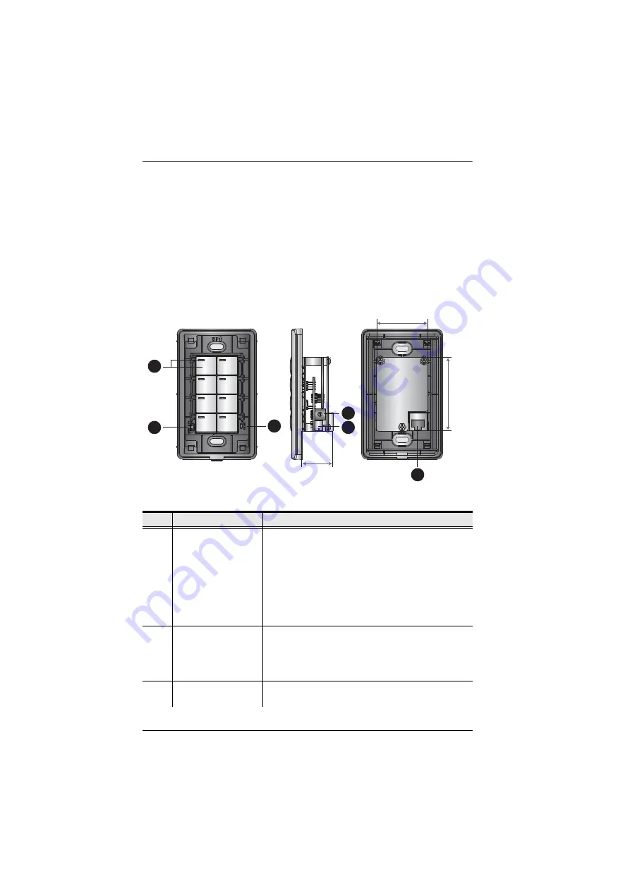
Hardware
No.
Component
Description
1
Buttons and LED
Customizable button placement on the keypad can be
setup in 14 different configurations with a combination
of 4 to 8 buttons. Examples on the next page provide
sample layouts. Use the caps to create the desired
keypad layout. The LED on each button:
Lights orange to indicate the power is on.
Lights white to indicate the keypad is in operation.
Blinks orange and white to indicate F/W upgrade.
2
LAN and Link LED
These two system LEDs indicate the keypad status:
LAN: lights green to indicate a LAN connection.
Link: lights green to indicate a Control Box
connection.
3
Reset
This semi-recessed pushbutton can be pressed to
reset the network settings.
1
2
5
3
6
4
47.67mm
68mm
28.2mm
Summary of Contents for VK1100
Page 1: ...ATEN Control System User Manual www aten com ...
Page 24: ...ATEN Control System User Manual 14 This Page Intentionally Left Blank ...
Page 48: ...ATEN Control System User Manual 38 This Page Intentionally Left Blank ...
Page 113: ...Chapter 5 ATEN Configurator VK6000 103 Icon Device Interface ...
Page 134: ...ATEN Control System User Manual 124 This Page Intentionally Left Blank ...
Page 152: ...ATEN Control System User Manual 142 This Page Intentionally Left Blank ...
Page 161: ...Chapter 7 ATEN Control System App 151 Controller PJLink Projector Telnet ...
Page 162: ...ATEN Control System User Manual 152 ONVIF TCP ...


