background image

KVM Over the NET™ User Manual

34

PDU Installation

ATEN PDU products are intelligent Power Distribution Units that offer outlet 
level control combined with remote access to give IT administrators the ability 
to power control devices attached to the unit from practically any location via 
a TCP/IP connection.

Note:

The PDU GUI shown in the example is the PE9216r. See

Supported 

Power Distribution Units

, page 290, for a list of other PDUs.

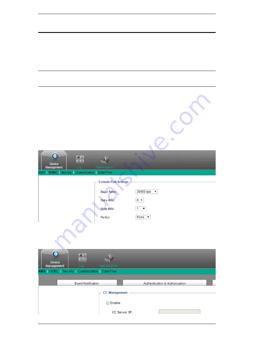
To set up a PDU in conjunction with KVM Over the NET™ switches, refer to 
the images below and do the following:

1. Connect both the KVM Over the NET™ switch and the PDU to your 

Ethernet switch.

2. In the PDU’s GUI, browse to Device Management, then to OOBC. In 

Console Port Settings, set the Baud Rate to 38400 bps.

3. Still in Device Management, browse to ANMS. In CC Management, 

uncheck Enable.

Summary of Contents for KN2116v

Page 1: ...KVM Over the NET KN2124v KN2140v KN4124v KN4140v KN2116v KN2132v KN4116v KN4132v KN2116A KN2132 KN4116 KN4132 User Manual www aten com ...

Page 2: ...o correct the interference at his own expense The device complies with Part 15 of the FCC Rules Operation is subject to the following two conditions 1 this device may not cause harmful interference and 2 this device must accept any interference received including interference that may cause undesired operation Suggestion Shielded twisted pair STP cables must be used with the unit to ensure complia...

Page 3: ...KVM Over the NET User Manual iii SJ T 11364 2006 The following contains information that relates to China ...

Page 4: ...r product at our online support center Telephone Support For telephone support call this number International http eservice aten com International 886 2 8692 6959 China 86 10 5255 0110 Japan 81 3 5615 5811 Korea 82 2 467 6789 North America 1 888 999 ATEN ext 4988 United Kingdom 44 8 4481 58923 ...

Page 5: ...cing repair and any incidental or consequential damages resulting from any defect in the software The manufacturer of this system is not responsible for any radio and or TV interference caused by unauthorized modifications to this device It is the responsibility of the user to correct such interference The manufacturer is not responsible for any damage incurred in the operation of this system if t...

Page 6: ... User Instructions Check to make sure that all of the components are present and in good order If anything is missing or was damaged in shipping contact your dealer Read this manual thoroughly and follow the installation and operation procedures carefully to prevent any damage to the switch or to any other devices on the installation Features may have been added since this manual was published Ple...

Page 7: ...Security 7 Virtual Media 7 Virtual Remote Desktop 7 V Series Exclusive 8 System Requirements 9 Remote User Computers 9 Servers 9 KVM Adapter Cables 10 Operating Systems 11 Browsers 11 Components 12 KN2124v KN2140v KN4124v KN4140v Front View 12 KN2116v KN2132v KN4116v KN4132v Front View 12 KN2116A KN2132 KN4116 KN4132 Front View 13 KN2124v KN2140v KN4124v KN4140v Rear View 15 KN2116v KN2132v KN4116...

Page 8: ... 38 Port Selection 38 Chapter 3 Super Administrator Setup Overview 39 First Time Setup 39 Network Setup 41 Changing the Super Administrator Login 42 Moving On 44 Chapter 4 Logging In Overview 45 Local Console Login 45 Browser Login 46 Windows Client AP Login 47 The Windows Client AP Connection Screen 48 Connecting Windows Client AP 49 The File Menu 50 Java Client AP Login 51 The Java Client AP Con...

Page 9: ...de 91 Automatic Mouse Synchronization DynaSync 91 Mac and Linux Considerations 92 Manual Mouse Synchronization 92 Control Panel Configuration 93 The Java Control Panel 95 Chapter 6 Port Access Overview 97 Browser GUI 97 AP GUI 97 The Sidebar 99 The Sidebar Tree Structure 99 Scan 100 Array 100 Filter 101 Sidebar Utilities 102 Port Outlet Naming 103 KVM Devices and Ports Connections Page 105 Device ...

Page 10: ... Port Level 131 Port Properties 131 Associated Links 133 Power Management 134 Extended Display 139 Chapter 7 User Management Overview 143 Browser GUI 143 AP GUI 143 Users 145 Adding Users 145 Modifying User Accounts 149 Deleting User Accounts 149 Groups 150 Creating Groups 150 Modifying Groups 152 Deleting Groups 152 Users and Groups 153 Assigning Users to a Group From the User s Notebook 153 Remo...

Page 11: ...177 Enable Dial Out 177 Security 179 Login Failures 179 Filter 180 Login String 183 Account Policy 184 Encryption 185 Mode 186 Private Certificate 187 Certificate Signing Request 188 Date Time 190 Time Zone 190 Date 191 Network Time 191 PON Devices 192 Configuration Page 192 Outlet Configuration 193 Blade Servers 194 Configuration Page 194 Blade Server Setup 195 Adding a Blade Server 195 Modifying...

Page 12: ...8 Backup Restore 209 Backup 209 Restore 210 Ping 211 Terminal 212 Restore Values 213 Clear Port Names 213 Restore Default Values 213 Reset on exit 213 Chapter 11 Download Overview 215 Chapter 12 Port Operation Overview 217 Connecting to a Port 218 The Port Toolbar 219 The Toolbar Icons 220 Toolbar Hotkey Port Switching 221 Auto Scanning 221 Skip Mode 222 Recalling the Port Access Page 223 GUI Hotk...

Page 13: ...N2124v KN4124v 246 KN2140v KN4140v 247 KN2116v KN4116v 248 KN2116A KN4116 249 KN2132v KN4132v 250 KN2132 KN4132 251 Troubleshooting 252 General Operation 252 Mouse Problems 254 Virtual Media 256 Web Browser 256 The WinClient ActiveX Viewer and the WinClient AP 257 The Java Applet and Java Client AP 258 Sun Systems 259 Mac Systems 259 Redhat Systems 260 The Log Server 260 Panel Array Mode 260 IP Ad...

Page 14: ...lution Procedures 280 Trusted Certificates 281 Overview 281 Installing the Certificate 282 Certificate Trusted 283 Mismatch Considerations 284 Self Signed Private Certificates 285 Examples 285 Importing the Files 285 Fan Location and Speed Information 286 Fan Location 286 Fan Speed 286 Temperature Sensor Location and Information 287 Clear Login Information 288 Factory Default Settings 289 Serial A...

Page 15: ...itch with each of the available access methods from a local console an internet browser a stand alone Windows application AP program and a stand alone Java application AP program Chapter 5 The User Interface describes the layout and explains the components of the KVM Over the NET switch user interface Chapter 6 Port Access describes the Port Access page and how to configure the options it provides...

Page 16: ...the following conventions Monospaced Indicates text that you should key in Indicates keys you should press For example Enter means to press the Enter key If keys need to be chorded they appear together in the same bracket with a plus sign between them Ctrl Alt 1 Numbered lists represent procedures with sequential steps Bullet lists provide information but do not involve sequential steps Indicates ...

Page 17: ...ter performing operations on the servers connected to the switch that is remote from him Remote servers We refer to the servers as Remote servers when we think of them from the Local Client User s point of view since although they are locally attached to the switch they are remote from him When we describe the overall system architecture we are usually speaking from the switch s point of view in w...

Page 18: ...KVM Over the NET User Manual xviii This Page Intentionally Left Blank ...

Page 19: ...ed on a complete two stage installation The switches in this series are differentiated according to the number of buses they support and the number of KVM ports they provide as shown below Model Bus Support KVM Ports KN2124v 1 Local 2 Remote 24 KN2140v 1 Local 2 Remote 40 KN4124v 1 Local 4 Remote 24 KN4140v 1 Local 4 Remote 40 KN2116v 1 Local 2 Remote 16 KN2132v 1 Local 2 Remote 32 KN4116v 1 Local...

Page 20: ...o and mouse signals with the servers attached to the switches just as if they were present locally and working on the equipment directly Up to 32 users can share the switch s buses A Message Board feature allows them to communicate with each other to facilitate port sharing Administrators can handle a multitude of maintenance tasks with ease from installing and running GUI applications to BIOS lev...

Page 21: ...peration modes and more so that when you move a KVM Adapter Cable from one port to another the switch recognizes the same adapter cable at the new location Also for greater ease of use when moving the adapter cable to another switch the adapter ID OS keyboard language adapter name and operation modes of the port stay with the adapter The KVM Over the NET V series switches KN2124v KN2140v KN4124v K...

Page 22: ...t they run at optimum speed depending on the server room temperature throttling down when necessary to use energy more efficiently and prolong the life of both the fans and the switch The KN2124v KN2140v KN4124v KN4140v KN2116v KN2132v KN4116v and KN4132v models are also audio enabled Microphone and speakers are supported on the Local Console for the servers speakers are supported on the remote us...

Page 23: ...s at up to 50 m Monitor and control up to 16 or 32 computers on a single level or control up to 512 computers in a cascade Cascade compatible KVM Switches include the following CS9134 CS9138 CS88A KH1508 KH1516 KH1508A and KH1516A Management Up to 64 user accounts up to 32 users simultaneously share the control End session feature administrators can terminate running sessions Event logging and Win...

Page 24: ...offer a unified multi language interface to minimize the user training time and increase productivity Multiplatform client support Windows Mac OS X Linux Sun Multi browser support Internet Explorer Chrome Firefox Safari Opera Mozilla Netscape Browser based UI in pure Web technology allows administrators to perform administrative tasks without pre installed Java software package required User can l...

Page 25: ... file applications OS patching software installation and diagnostic testing Works with USB enabled servers at the operating system and BIOS level Supports DVD CD drives USB mass storage devices PC hard drives and ISO images Supports Smart Card Readers on computers connected with KA7166 KA7168 KA7169 KA7177 Adapter Cables Virtual Remote Desktop Video quality and video tolerance can be adjusted to o...

Page 26: ...4140v KN2116v KN2132v KN4116v and KN4132v include the following Audio a microphone and speakers are supported on the Local Console speakers only are supported on the remote user computers Dual power supply support Log and UI reflect the power status Virtual Media support Variable fan speed speed changes according to the switch s temperature ...

Page 27: ...e browser based Java Applet Viewer the latest version of the Java Runtime Environment JRE must be installed and at least 205MB of memory must be available after installation For the Windows Client AP DirectX 8 must be present and at least 90MB of memory must be available after installation For the Java Client AP the latest version of the Java Runtime Environment JRE must be installed and at least ...

Page 28: ...re see page 204 Function Module Connect to devices with PS 2 ports KA9120 KA7120 Connect to devices with USB ports All platforms PC Mac Sun KA9170 KA7170 Connect to Sun Legacy Computers KA9130 KA7130 Connect to serial based devices KA9140 KA7140 For USB computers DVI output Virtual Media and Smart Card Reader support KA7166 For USB computers HDMI output Virtual Media and Smart Card Reader support ...

Page 29: ...switch include the following See Mac Systems page 259 for further information OS Version Windows 2000 and higher Linux RedHat 7 1 and higher Fedora Core 2 and higher SuSE 9 0 and higher Mandriva Mandrake 9 0 and higher UNIX AIX 4 3 and higher FreeBSD 4 2 and higher Sun Solaris 8 and higher Novell Netware 5 0 and higher Mac OS 9 and higher DOS 6 2 and higher Browser Version IE 6 and higher Chrome 8...

Page 30: ...nt panel of a KN2140v KN4140v The KN2124v KN4124v differs from the diagram in that there are fewer port LEDs KN2116v KN2132v KN4116v KN4132v Front View Note The figure above shows the front panel of a KN4132v KN2132v The KN2116v KN4116v differs from the diagram in that there are fewer port LEDs 2 5 7 4 1 3 6 2 5 7 4 1 3 6 ...

Page 31: ...oduction 13 KN2116A KN2132 KN4116 KN4132 Front View Note The figure above shows the front panel of a KN4132 KN2132 The KN2116A KN4116 differs from the diagram in that it only has a single row of port LEDs 2 5 7 4 1 3 ...

Page 32: ... the V series switches 5 Reset Switch Note This switch is recessed and must be pushed with a small object such as the end of a paper clip or a ballpoint pen Pressing and releasing this switch when the unit is running performs a system reset Pressing and holding this switch in for more than three seconds when the unit is running resets its configuration to the factory default settings Note This doe...

Page 33: ... The KN2124v KN4124v differs in that it only has a single block of 16 KVM ports and one bock of 8 24 ports in total KN2116v KN2132v KN4116v KN4132v Rear View Note The figure above shows the rear panel of a KN2132v KN4132v with two blocks of 16 KVM ports 32 ports in total The KN2116v KN4116v differs in that it only has a single block of KVM ports 16 ports in total 1 2 3 4 6 5 7 8 9 1 2 3 4 6 5 7 8 ...

Page 34: ... KN4116 KN4132 Rear View Note The figure above shows the rear panel of a KN2132 KN4132 with two blocks of 16 KVM ports 32 ports in total The KN2116A KN4116 differs in that it only has a single block of KVM ports 16 ports in total 1 2 3 4 6 5 7 8 9 ...

Page 35: ... for installation details Contact your dealer for more information regarding PON units 5 Grounding Terminal The wire used to ground the unit connects here 6 Primary LAN Port The cable that connects the unit to the primary network interface 10 100 1000 Mbps plugs in here 7 Modem Port For dial in connection should the unit be unavailable over the network See Single Stage Installation page 25 step 7 ...

Page 36: ...KVM Over the NET User Manual 18 This Page Intentionally Left Blank ...

Page 37: ...e installation diagram on p 16 A separate KVM Adapter Cable is required for each server or device connection The model numbers of the Adapters are given in the KVM Adapter Cables section page 10 Before You Begin 1 Important safety information regarding the placement and grounding of this device is provided on page 237 and onwards Please review it before proceeding 2 Make sure that the power to any...

Page 38: ...appropriate level surface that can safely support its weight plus the weight of its attached cables To place the switch or to stack units if you are daisy chaining them remove the backing material from the bottom of the rubber feet that came with your package and stick them onto the switch s bottom panel at the corners as shown in the diagram below Note To ensure adequate ventilation allow at leas...

Page 39: ...it so that it can attach to the front or the back of the rack Rack Mounting Front To mount the unit at the front of the rack do the following 1 Remove the two screws at the front of the unit 2 Use the M3 x 8 Phillips head hex screws supplied with the rack mount kit to screw the rack mounting brackets into the front of the unit Phillips head hex M3 x 6 Phillips head hex M3 x 8 ...

Page 40: ...l 22 3 Position the device in the front of the rack and align the holes in the mounting brackets with the holes in the rack 4 Screw the mounting brackets to the rack Note Cage nuts are provided for racks that are not prethreaded ...

Page 41: ...crews at the rear of the unit 2 Use the M3 x 8 Phillips head hex screws supplied with the rack mounting kit to screw the rack mounting brackets into the rear of the unit 3 Position the device in the rack and align the holes in the mounting brackets with the holes in the rack Phillips head hex M3 x 6 Phillips head hex M3 x 8 ...

Page 42: ...KVM Over the NET User Manual 24 4 Screw the mounting brackets to the rear of the rack Note Cage nuts are provided for racks that are not prethreaded ...

Page 43: ...ge 28 For the KN2116A KN2132 KN4116 and KN4132 plug your Local Console s keyboard monitor and mouse into the unit s Console Ports Each port is color coded and marked with an appropriate icon See KN2116A KN2132 KN4116 KN4132 Single Stage Installation Diagram page 29 Note 1 You can use any combination of keyboard and mouse connections For example you can use a PS 2 keyboard with a USB mouse 2 USB ke...

Page 44: ...he PON IN port of a Power Over the Net unit Note 1 For Power Over the Net Units and Power Distribution Units go to Device Management OOBC Console Port Settings of GUI and select the Baud Rate of 38400 bps 2 Make sure the CC Management function is disabled for both the KN and PN 3 The PON unit shown in the example is the PN0108 See Supported Power Over the Net Units and Supported Power Distribution...

Page 45: ...rn on both power switches Note If you are connecting the power to a UPS or an ALTUSEN PN9108 PN0108 be sure to use the utility power cords supplied with your package instead of standard power cords After the KVM Over the NET switch is cabled up you can turn on the power After it is powered up you can turn on the servers KN2124v KN2140v KN4124v KN4140v Single Stage Installation Diagram 9 7 1 6 3 2 ...

Page 46: ...ser Manual 28 KN2116v KN2132v KN4116v KN4132v Single Stage Installation Diagram 1 9 7 1 1 6 3 2 2 4 5 Modem PN0108 8 by ATE N PS 2 C PU M O D U LE M O D EL N O K A 91 20 PS 2 C PU M O D U LE M O D EL N O K A 91 20 LI N K ...

Page 47: ...re Setup 29 KN2116A KN2132 KN4116 KN4132 Single Stage Installation Diagram 9 7 1 1 6 3 2 2 4 5 Modem PN0108 8 by ATE N P S 2 C P U M O D U LE M O D EL N O K A 91 20 P S 2 C P U M O D U LE M O D EL N O K A 91 20 LI N K ...

Page 48: ...anual 30 Adapter Cable Connection Diagram KA7120 KA9120 by ATEN LINK KA7170 KA9170 by ATEN LINK KA7130 KA9130 by ATEN LINK KA7177 by ATEN LINK KA7140 by ATEN LINK KA9140 SERIAL TERMINAL KA7175 by ATEN LINK KA7176 by ATEN LINK ...

Page 49: ...Chapter 2 Hardware Setup 31 Adapter Cable Connection Diagram cont KA7166 KA7168 KA7169 ...

Page 50: ...ET switch to a KVM Adapter Cable as described under KVM Adapter Cables page 10 3 Plug the adapter cable s KVM connectors to the Keyboard Video and Mouse Console ports of the Second Stage unit Note The distance between the First Stage unit and the Second Stage unit must not exceed 40m or 50m based on the KVM adapter cable used 4 Use KVM cable sets as described in the Cables section of the cascaded ...

Page 51: ...Chapter 2 Hardware Setup 33 Two Stage Installation Diagram KN4140v 2 6 KH1516 KA9120 3 4 5 ...

Page 52: ... Note The PDU GUI shown in the example is the PE9216r See Supported Power Distribution Units page 290 for a list of other PDUs To set up a PDU in conjunction with KVM Over the NET switches refer to the images below and do the following 1 Connect both the KVM Over the NET switch and the PDU to your Ethernet switch 2 In the PDU s GUI browse to Device Management then to OOBC In Console Port Settings ...

Page 53: ...sing the KVM Over the NET switch GUI browse to Device Management then to ANMS In Authentication uncheck CC Management 6 Finally confirm that appropriate power management permission has been assigned Browse to Port Access then to Port Configuration Select the relevant port number from the left tree menu Select Add a power device ...

Page 54: ... adapter cable s configuration information access rights etc in its database so that when you move a server together with its adapter cable from one port to another you don t have to reconfigure its settings the Adapter ID function restores them at the new location The only change is in the port number When moving the server and adapter cable to another switch however only the information that is ...

Page 55: ...starting If it becomes necessary to power off the switch or if the switch loses power and needs to be restarted wait 10 seconds before powering it back on The servers should not be affected by this but if any of them should fail simply restart them ...

Page 56: ... two segment Port ID The second segment from 1 16 represents the KVM Port number on the Second Stage unit that the server is connected to The first segment from 1 40 represents the KVM Port number on the First Stage unit that the Second Stage unit links back to For example a Port ID of 12 3 refers to a server that is connected to KVM Port 3 of a Second Stage unit that links back to KVM Port 12 of ...

Page 57: ...istrator login The most convenient way to do this for the first time is from the local console Note For remote methods of setting up the network see IP Address Determination page 263 After the local console has been connected see Single Stage Installation page 25 and the KVM Over the NET switch turned on a login prompt appears on the console monitor Since this is the first time you are logging in ...

Page 58: ...KVM Over the NET User Manual 40 After you successfully log in the Local Console Main Page appears ...

Page 59: ... Administrator Setup 41 Network Setup To set up the network do the following 1 Click the Device Management tab 2 Select the Network tab 3 Fill in the fields according to the information provided under Network page 165 ...

Page 60: ...t tab The User Management page has a list of Users and Groups in the Sidebar at the left and a more detailed list of users with more information about them in the large central panel Since this is the first time the page is being accessed only the Super Administrator appears 2 Click administrator in the left panel or Select administrator in the central panel then click Modify at the bottom of the ...

Page 61: ...e and Password to something unique 4 Enter the password again in the Confirm Password field to confirm it is correct 5 Click Save 6 When the dialog box informing you that the change completed successfully appears Click OK 7 Click on another item on the Local Console Main Page to close this page ...

Page 62: ...an be accomplished using any of the KVM Over the NET switch s GUI utilities These include the Local Console the browser based Windows ActiveX Viewer the browser based Java Applet Viewer the stand alone Windows Client AP and the stand alone Java Client AP Choose the approach that suits you best Note Firmware Upgrade Maintenance cannot be performed from the local console You must log in remotely wit...

Page 63: ...h a correct username and password Note If the number of invalid login attempts exceeds a specified amount a time out period is invoked You must wait until the time out period expires before you can attempt to log in again See Login Failures page 179 for further details Local Console Login When the local console is attached see Single Stage Installation page 25 and there is no user logged in the KV...

Page 64: ...ou must include a forward slash and the login string along with the IP address when you log in For example 192 168 0 100 kn4140v If you don t know the IP address and login string ask your Administrator 2 When a Security Alert dialog box appears accept the certificate it can be trusted See Trusted Certificates page 281 for details If a second certificate appears accept it as well Once you accept th...

Page 65: ... access to Windows systems users without having to go through a browser although you initially download the Windows AP Client program from the browser page see Chapter 11 Download To connect to the KVM Over the NET switch go to the location on your hard disk that you downloaded the Windows AP Client program to and double click its icon WinClient exe to bring up the Windows Client Connection Screen...

Page 66: ...page 166 match the number specified for Port in the Server area of this dialog box appear in the Server List window Server This area is used when you want to connect to a KVM Over the NET switch at a remote location You can drop down the IP list box and select an address from the list If the address you want isn t listed you can key in the target IP address in the IP field and its port number in t...

Page 67: ...t to Or Specify its IP address and port number in the Server IP and Port input boxes 2 Click Connect The Login dialog box appears 3 Key in a valid Username and Password and then click OK 4 Once you have been authenticated the Switch to Remote View button becomes active Click it to connect to the switch and bring up its GUI Main Page For a description of the GUI Main Page see page 48 ...

Page 68: ...t opens with the values contained in the current work file The current work file consists of the values that were in effect the last time the program was closed The File menu consists of the following items New Allows the user to create a named work file so its values will not be lost and it will be available for future recall Open Allows the user to open a previously saved work file and use the v...

Page 69: ... Windows the Java AP Client provides direct remote access to non Windows systems users although you initially download the Java AP Client program from the browser page see Chapter 11 Download To connect to the KVM Over the NET switch go to the location on your hard disk that you downloaded the Java AP Client program to and double click its icon JavaClient jar to bring up the Java Client Connection...

Page 70: ...t window Server This area is used when you want to connect to a KVM Over the NET switch at a remote location You can drop down the IP list box and select an address from the list If the address you want isn t listed you can key in the target IP address in the IP field and its port number in the Port field If you don t know the port number contact your Administrator When the IP address and Port num...

Page 71: ...onnect to Or Specify its IP address and port number in the Server IP and Port input boxes 2 Click Login The Login dialog box appears 3 Key in a valid Username and Password and then click OK 4 Once you have been authenticated the Remote View button becomes active Click it to connect to the switch and bring up its GUI Main Page For a description of the GUI Main Page see page 48 ...

Page 72: ...KVM Over the NET User Manual 54 This Page Intentionally Left Blank ...

Page 73: ...is described in the sections that follow The Web Browser Main Page To ensure multi platform operability access to the KVM Over the NET switches can be accomplished with most standard web browsers Once users log in and are authenticated see page 46 the Web Browser Main Page comes up with the Port Access page displayed Note The screen depicts a Super Administrator s page Depending on a user s type a...

Page 74: ...ies that pertain to the item selected in the tab bar The items that appear in the menu bar are determined by the user s type and the authorization options that were selected when the user s account was created 3 Sidebar The Sidebar provides a tree view listing of ports that relate to the various tab bar and menu bar selections Clicking a node in the Sidebar brings up a page with the details that a...

Page 75: ...e Device Management page is used to configure and control the overall operation of the KVM Over the NET switch This page is available to the Super Administrator as well as administrators and users who have been given Device Management permission The tab doesn t appear for other administrators and users Log The Log page displays the contents of the log file The Log page is discussed on page 197 Mai...

Page 76: ...ar it has a series of tabs like a notebook instead Like the Web Browser interface however the makeup of the tabbed notebook changes depending on the items selected on the main Tab Bar and in the Sidebar 2 In addition to Filter there are also buttons for Scan and Array Mode at the bottom of the Sidebar These functions are discussed in Chapter 6 Port Access 3 There is a hidden Control Panel at the u...

Page 77: ...keyboard as shown in the table below Keys Action Ctrl P Opens the Port Access page Ctrl U Opens the User Management page Ctrl C Opens the Device Management page Ctrl L Opens the Log page Ctrl M Opens the Maintenance page Ctrl D Opens the Download page F1 To see About information F2 To edit the port name of the selected port F4 Selects the Sidebar left panel F5 Selects the main right panel F7 Close...

Page 78: ... small icons at the bottom right as described in the following table Icon Function Speaker Allows sound output from the servers connected to the switch s ports to be heard on the speakers connected to the Local Console Click the icon to toggle speaker support On and Off When Off a red X displays across the icon Microphone Allows microphone input from the Local Console to be sent to the servers con...

Page 79: ...ns that appear can be user selected See Control Panel Configuration page 93 for details By default the upper text row shows the video resolution of the remote display As the mouse pointer moves over the icons in the icon bar however the information in the upper text row changes to describe the icon s function In addition if a message from another user is entered in the message board and you have n...

Page 80: ...on of the toolbar In addition it allows you to select options for the Zoom Mouse Pointer and Mouse Sync Mode These functions are discussed in the sections that follow To move the Control Panel to a different location on the screen place the mouse pointer over the text row area then click and drag ...

Page 81: ...ke a snapshot screen capture of the remote display See Snapshot page 94 for details on configuring the Snapshot parameters Click to bring up the Message Board see The Message Board page 80 Click to send a Ctrl Alt Del signal to the remote system Click to toggle the remote display between color and gray scale views Click to bring up the Virtual Media dialog box The icon changes depending on the sta...

Page 82: ...See Power Over the Net page 89 for a complete explanation of this feature The Extended Displays icon allows you to select monitors to view in an extended display setup see page 90 See Extended Display page 139 for a complete explanation of how to set this feature up Under an accessed port click to skip to the first port accessible to the user on the entire installation without having to recall the...

Page 83: ...el Click to exit the viewer Exiting from a Browser Viewer session brings you back to the web browser Main Page Exiting from a WinClient AP session brings you back to the login dialog box see page 47 Exiting from a Java Client AP session brings you back to the login dialog box see page 51 These icons show the Num Lock Caps Lock and Scroll Lock status of the remote computer When the lock state is On...

Page 84: ...ke an action are shown to the right of its name Use the checkbox to the left of an action s name to enable or disable its hotkey To change the hotkey for an action do the following 1 Highlight the Action then click Set Hotkey 2 Press your selected Function keys one at a time The key names appear in the Hotkeys field as you press them You can use the same function keys for more than one action as l...

Page 85: ...ature Adjust mouse This synchronizes the local and remote mouse movements The default keys are F7 F8 F9 Video Auto sync This combination performs an auto sync operation It is equivalent to clicking the Video Autosync icon on the Control Panel The default keys are F8 F7 F6 Show Hide Local Cursor Toggles off and on hides local cursor and locks the mouse pointer and keyboard use within the Windows Ja...

Page 86: ...ser Macros are created to perform specific actions on the remote server To create the macro do the following 1 Select User Macros then click Add 2 In the dialog box that comes up replace the New Macro text with a name of your choice for the macro ...

Page 87: ...ne takes Clicking Cancel cancels all keystrokes When you have finished click Stop This is the equivalent of clicking Done in Step 5 Note 1 Case is not considered typing A or a has the same effect 5 When recording the macro the focus must be on the remote screen It cannot be in the macro dialog box 2 Only the default keyboard characters may be used Alternate characters cannot be used For example if...

Page 88: ... Macros dialog box with your system macro key presses displayed in the Macro column 7 If you want to change any of the keystrokes select the macro and click Edit This brings up a dialog box similar to the one for Show You can change the content of your keystrokes change their order etc 8 Repeat the procedure for any other macros you wish to create ...

Page 89: ...y With Time Control the macro waits for the amount of time between key presses that you took when you created it Click on the arrow next to Play to make your choice If you click Play without opening the list the macro runs with the default choice NoWait or TimeCtrl which is shown in the Playback column You can change the default choice by clicking on the current choice NoWait in the screenshot abo...

Page 90: ...match your search string appear in the upper panel System Macros System Macros are used to create exit macros for when you close a session For example as an added measure of security you could create a macro that sends the Winkey L combination which would cause the remote server s log in page to come up the next time the device was accessed To create the macro do the following 1 Select System Macr...

Page 91: ...dered typing A or a has the same effect 5 When recording the macro the focus must be on the remote screen It cannot be in the macro dialog box 2 Only the default keyboard characters may be used Alternate characters cannot be used For example if the keyboard is Traditional Chinese and default character is A the alternate Chinese character obtained via keyboard switching is not recorded 6 If you hav...

Page 92: ...h to create Once the system macros have been created they are available for use on a port by port basis They get selected on a port s Port Configuration Port Properties page see Port Level page 131 for details Note 1 Information about the Search function is given on page 72 2 You can choose only one system macro per port 3 Systems macros are stored on the switch therefore macro names may not excee...

Page 93: ... in the basic dialog box allow you to adjust the Screen Position set Auto Sync and slide the Performance bar setting Selecting the Advanced button opens the Advanced Video Settings dialog box providing more detailed options including RGB Gamma Video Quality Enable Refresh Transparency Color Depth Control and Detect Tolerance settings as shown below Basic Video Settings ...

Page 94: ...s Auto Sync Click Auto Sync to have the vertical and horizontal offset values of the remote screen detected and automatically synchronized with the local screen Note 1 If the local and remote mouse pointers are out of sync in most cases performing this function will bring them back into sync 2 This function works best with a bright screen 3 If you are not satisfied with the results use the Screen ...

Page 95: ...The larger the value the clearer the picture and the more video data goes through the network Depending on the network bandwidth a high value may adversely effect response time Enable Refresh The KVM Over the NET switch can redraw the screen every 1 to 99 seconds eliminating unwanted artifacts from the screen Select Enable Refresh and enter a number from 1 through 99 The KVM Over the NET switch wi...

Page 96: ...tter video quality but setting the threshold too low may allow too much data to be transferred negatively impacting network performance Selecting the Auto Balance Tolerance check box allows the switch to automatically detect and adjust the tolerance settings according to pixel changes as they occur Preset Custom Using the Preset and Custom buttons allow you to set and save custom video settings an...

Page 97: ...n brings up the following dialog box Click and drag the diagonal line at as many points as you wish to achieve the display output you desire Click Save As to save up to four user defined configurations derived from this method Saved configurations can be recalled from the list box at a future time Click Reset to abandon any changes and return the gamma line to its original diagonal position Click ...

Page 98: ...e in the User List panel when the user has disabled Chat Occupy Release Keyboard Video Mouse When you Occupy the KVM other users cannot see the video and cannot input keyboard or mouse data The button is shadowed when the KVM is occupied The icon displays next to the user s name in the User List panel when the user has occupied the KVM Occupy Release Keyboard Mouse When you Occupy the KM other use...

Page 99: ...t Panel The names of all the logged in users are listed in this panel Your name appears in blue other users names appear in black By default messages are posted to all users To post a message to one individual user select the user s name before sending your message If a user s name is selected and you want to post a message to all users select All Users before sending your message If a user has di...

Page 100: ...dia To mount a virtual media device do the following 1 Click the Virtual Media icon to bring up the Virtual Media dialog box Note The T button at the top right brings up a slider to adjust the transparency of the dialog box After making your adjustment click anywhere in the dialog box to dismiss the slider Icon Function The icon displays in gray to indicate that the virtual media function is disab...

Page 101: ...ck Add and select the source as many times as you require Up to three virtual media choices can be mounted The top three in the list are the ones that are selected Virtual Media and Smart Card readers can be mounted at the same time To rearrange the selection order highlight the device you want to move then click the Up or Down Arrow button to promote or demote it in the list 5 Read refers to the ...

Page 102: ...remote server s file system Once mounted you can treat the virtual media as if they really existed on the remote server drag and drop files to from them open files on the remote server for editing and save them to the redirected media etc Files that you save to the redirected media will actually be saved on your local client computer s storage Files that you drag from the redirected media will act...

Page 103: ...dow at 75 50 Sizes and displays the remote view window at 50 25 Sizes and displays the remote view window at 25 1 1 Sizes and displays the remote view window at 100 The difference between this setting and the 100 setting is that when the remote view window is resized its contents don t resize they remain at the size they were To see any objects that are outside of the viewing area move the mouse t...

Page 104: ...f the remote and local systems aren t the same you don t have to change the configuration settings for either system Just bring up the on screen keyboard select the language used by the server you are accessing and use the on screen keyboard to communicate with it Note You must use your mouse to click on the keys You cannot use your actual keyboard Changing Languages To change languages do the fol...

Page 105: ...well as the PC To select the platform do the following 1 Click the down arrow next to the currently selected platform to drop down the platform list 2 Select the new platform from the list Expanded Keyboard To display hide the expanded keyboard keys click the arrow to the right of the language list arrow ...

Page 106: ...accessing a port only Dual and Crosshairs are available for the Windows Viewers Once the port is accessed three pointers are available 2 The Dot pointer is not available with the Java Applet Viewer or the Java Client AP 3 Selecting the Single pointer has the same effect as the Toggle mouse display hotkey function see Toggle mouse display page 67 for details 4 The icon on the Control Panel changes ...

Page 107: ...available choices After clicking on the PON icon a list of the power outlets associated with the connected port appears with the available options Options Usage On Off Sends a Power Off signal to the selected outlet On Reboot Sends a Reboot signal to the selected outlet Off On Sends a Power On signal to the selected outlet All Sends the selected signal On Off Reboot to all associated outlets Pendi...

Page 108: ...ay Panel Window Options Usage Switch Double click a screen in the Display Panel window to switch to that extended display Expand Collapse Hover the mouse pointer over the edge of the Display Panel window until it turns into a double arrow then click and drag to expand or collapse the window size Move Put the mouse pointer inside the Display Panel window click and drag to move the window anywhere o...

Page 109: ...nual mouse synchronization described in the next section The icon on the Control Panel indicates the synchronization mode status as follows When Mouse DynaSync is available clicking the icon toggles its status between enabled and disabled If you choose to disable Mouse DynaSync mode you must use the manual synching procedures described under Manual Mouse Synchronization page 92 Icon Function This ...

Page 110: ...ou must perform the manual mouse synchronization procedures described in the next section Manual Mouse Synchronization If the local mouse pointer goes out of sync with the remote system s mouse pointer there are a number of methods to bring them back into sync 1 Perform a video and mouse auto sync by clicking the Video Settings icon on the Control Panel see page 75 2 Perform an Auto Sync with the ...

Page 111: ...ibed in the table below Item Description Customize Control Panel Allows you to select which icons display in the Control Panel Check the ones you want to see uncheck the ones you don t want Control Panel Style Enabling Transparent makes the Control Panel semi transparent so that you can see through it to the display underneath Enabling Icon causes the Control Panel to display as an icon until you ...

Page 112: ...nt the screen will scroll when you move the mouse pointer to your screen border If you select Scroll Bars scroll bars appear around the screen borders that you can use to scroll to the off screen areas Bus Info If Bus Info is enabled the number of the bus you are on as well as the total number of users on the bus displays on the bottom row center of the Control Panel as follows Bus No Total Users ...

Page 113: ... Hide button to show or hide the user list This function is achieved by clicking the arrows at the top of the bar that separates the User List panel from the Main panel In Virtual Media only ISO and Folder are supported See Java Applet Viewer Java Client AP page 291 for further details The Control Panel Lock LED icons are not in sync with your keyboard When you first connect the LED display may no...

Page 114: ...KVM Over the NET User Manual 96 This Page Intentionally Left Blank ...

Page 115: ...97 Chapter 6 Port Access Overview When you log in to the switch the Port Access page comes up with the KVM Over the NET switch s KVM Connections page displayed Browser GUI AP GUI ...

Page 116: ... Servers have been deployed they are listed separately below the PON devices Configuration and operation of KVM devices and ports are discussed on page 105 configuration and operation of PON devices and outlets are discussed on page 108 configuration and operation of Blade Servers are discussed on page 113 Note Power Over the Net devices are also referred to as PDUs Power Device Units After select...

Page 117: ...ve access permission for Ports outlets and child devices can be nested under their parent devices Click the in front of a device to expand the tree and see the ports outlets nested underneath it Click the to collapse the tree and hide the nested ports outlets A port s outlet s ID number is displayed in brackets next to its icon The ports outlets but can also be named see Port Outlet Naming page 10...

Page 118: ... because they are managed via the CC server Scan Scan is found at the bottom of the AP GUI Sidebar It automatically switches among all the ports that are visible in the Sidebar see Filter below at regular intervals so that their activity can be monitored automatically See Auto Scanning page 221 for details Note This item doesn t appear at the bottom of the Sidebar in the Browser version In that ve...

Page 119: ... 118 you can drop down the list box and select Favorites instead of All If you select Favorites only the items you have selected as Favorites display in the tree Powered On If you enable Powered On by putting a check in the checkbox only the ports that have their attached devices powered on display in the tree Search If you key in a search string and click Search only port names that match the sea...

Page 120: ...able lists and explains all of the possible items that may appear Item User Type Explanation Expand Collapse Administrators Users If the device s ports are nested not displayed the dialog box entry is Expand Click Expand to display the nested ports If the device s ports are displayed the dialog box entry is Collapse Click Collapse to nest the ports Note 1 This item only appears for switches or for...

Page 121: ...device attached to the port 2 In the AP GUI version you can right click on the port you want to edit then select Rename in the popup box that appears or you can highlight the port and press F2 After a second or two the field changes to provide a text input box 2 Key in a name for the item or change delete a previous one You can use any combination of letters numbers and symbols on the typewriter k...

Page 122: ...KVM Over the NET User Manual 104 3 When you have finished editing the name press Enter or click anywhere outside of the input box to complete the operation ...

Page 123: ...o access or view The following attributes are listed for each device Port Number the port s number on the switch Port Name if a name has been assigned to a port it displays here Device Name if a name has been assigned to the switch it displays here Status the current status of the port online or offline Note The sort order of the information displayed can be changed by clicking the column headings...

Page 124: ...urrent status information including whether the port is online or offline and if the port is mountable Click the Connect button to view the port display via the switch s built in Win Viewer when using Windows Internet Explorer or Java Viewer when using other web browsers Associated Links The Associated Links panel displays ports that have been associated with the currently selected port Associatio...

Page 125: ...o power manage several of them at once use Shift Click for a sequential set or Ctrl Click for a non sequential set to select your group If there is more than one outlet associated with this port and you want to power manage all of them at once click to put a checkmark in the Select All checkbox Note 1 Even though the outlets all turn On Off or Reboot at the same time they do so with their own sepa...

Page 126: ...evices Device Monitor Page Power Over the Net PON devices that are connected to the switches display below the KVM switches in the Sidebar When a PON device is selected in the Sidebar the Device Monitor page appears The Main Panel PON View ...

Page 127: ...M port the outlet is associated with Action Buttons The actions that the buttons at the bottom of the page perform are described in the table below Button Action Group View Click this button to switch the display to Group View see The Main Panel Group View page 111 for details Group Select the outlets that you want to form into a group then click this button to create it see Outlet Groups page 110...

Page 128: ...ick Group The Outlet Group dialog box comes up 3 Select whether or not the outlets will belong to a new group or to an existing group a If it is a new group give it a name in the text field b If it is an existing group select the group in the central panel 4 Click Save To remove outlets from groups select them in the main panel then click Ungroup ...

Page 129: ...nel then click Delete Selecting a group in the main panel then clicking Ungroup removes all outlets from that group It provides a shortcut method to remove all of them at once rather than having to remove then one by one from the PON View page To power manage a group of outlets first select the group s in the main panel then click the appropriate power button ...

Page 130: ... name of the PON that the outlet belongs to and the outlet s name as well as On Off Reboot and Configuration buttons to manually manage the outlet s power The Schedule panel lets you set up an automated Power management configuration for the outlet The procedure for accomplishing this is the same as the one described in the Power Management section See Schedule page 137 for details ...

Page 131: ...ade Configuration Page The Blade Configuration page is where the associations between the blade servers and the KVM switch ports get made To access this page select the blade server or blade then click Blade Configuration the menu item at the far right of the menu bar For IBM and Dell blade servers the entire chassis gets associated with a port and each blade in the chassis will appear in the tree...

Page 132: ...ch s ports and the blade servers IBM and Dell servers or individual blades HP servers that have been associated with them To make an association from the device view you first select a KVM port then select a blade server or blade to associate it with as follows 1 Select the port in the main panel 2 Click Associate 3 In the screen that comes up select the blade server or individual blade that you w...

Page 133: ... a button that toggles the main panel between the two views Click it to bring up the main panel in Blade View Blade View lists all of the blade servers IBM and Dell servers and individual blades HP servers that are installed on the system and the ports if any that they are associated with To make an association from the blade view you first select a blade server or blade then select a KVM port to ...

Page 134: ...association completes successfully the blade icon appears as the port indicator in the Sidebar tree To access the device running on the blade click on its entry in the Sidebar Unassociating Ports To break the association between a port and a blade server or individual blade select the association in the main panel then click Unassociate ...

Page 135: ...a port shown in the main panel by double clicking it If there are more entries than there is room on the screen a scroll bar appears to let you scroll up and down to see the entire record To clear the record and start over click the Clear History button at the bottom right of the page Note You can change the sort order of the information displayed by clicking the column headings ...

Page 136: ...here Simply open this page and select the port rather than hunting for it in the Sidebar This feature is especially handy on large crowded installations Adding a Favorite To add a port to the favorites do the following 1 Right click in the main panel click Add Favorite or Click Add at the bottom left of the main panel An Untitled Favorite entry appears ...

Page 137: ...t Paste or Select the container in the main panel select the port in the Sidebar then click Add to at the bottom of the main panel The switch that the port belongs to is added to the container the selected port is appended under the switch Note To add multiple ports at the same time hold the Shift or Ctrl key down while you make your Sidebar selections then drag or copy the entire group to the Fav...

Page 138: ...popup menu that appears To edit a Favorite s name Click on it once wait a second then click again You can edit the name after the display changes to provide a text input box This is the same procedure as the one described for port naming see Port Outlet Naming page 103 or Select the Favorite in the main panel then click Modify at the bottom of the main panel ...

Page 139: ...ys in OSD Hotkey Selects which Hotkey controls the GUI function Scroll Lock Scroll Lock is the default To select a different combination click the arrow at the right of the box to drop down the list of choices ID Display Selects how the Port ID is displayed the Port Number alone PORT NUMBER the Port Name alone PORT NAME or the Port Number plus the Port Name PORT NUMBER PORT NAME The default is POR...

Page 140: ... enabled when a port is accessed see The Port Toolbar page 219 for details Since the Toolbar functions are also available from the GUI Control Panel see The Control Panel page 61 you may prefer to disable it here Viewer You can choose which viewer is used when accessing a server Auto Detect will select the appropriate viewer based on the web browser used WinClient for Windows Internet Explorer Jav...

Page 141: ...er User The meanings of the headings at the top of the page are fairly straightforward The IP heading refers to the IP address that the user has logged in from the Device and Port headings show which device and port the user is currently accessing The Bus ID refers to the bus that the user is currently on Bus 0 refers to the Local Console s bus Note 1 The sort order of the information displayed ca...

Page 142: ...panel looks similar to the one shown below The main panel consists of two columns Name and Config Name lists all the users and groups that have been created Config indicates the users who have Configuration privileges A check mark indicates that the user has permission to make changes to the switch configuration settings see Chapter 8 Device Management an X means that the user is denied permission...

Page 143: ... of the other ports To do so 1 Select the port whose permissions you want the other port s to follow 2 Click Copy 3 Select the port you want to receive the permissions 4 Click Paste When you have finished making your configuration changes click Save Port Level Browser GUI Interface If a port is chosen in the Sidebar the Main panel looks similar to the one shown below ...

Page 144: ...h the choices click the icon in the row that corresponds to the user you want to configure The icons are the same as the ones in the Access column With a Full Access setting the user can mount read and write to the virtual media With a View Only setting the user can only view the contents of the virtual media read only he can not perform any operations on it With a No Access setting the user will ...

Page 145: ...me To filter on the User or Group name key in the name partial name or partial name then press Enter Only the Users and Groups whose names correspond to what you have keyed in appear in the list Wildcards for single characters for multiple characters and the keyword or are supported E g h ds would return hands and hoods h nd would return hand and hind but not hard h ds or h ks would return hands a...

Page 146: ...are displayed as described in the following table Filter Description Name To filter on the User or Group name key in the name partial name or partial name and wild card then press Enter Only the Users and Groups whose names correspond to what you have keyed in appear in the list Access All All Users and Groups appear in the list Full Access Only Users and Groups with Full Access permissions appear...

Page 147: ...appear in the list No Access Only Users and Groups with No Access Mount USB permissions appear in the list Config All All Users and Groups appear in the list Permitted Only Users and Groups with Permitted Config permissions appear in the list Restricted Only Users and Groups with Restricted Config permissions appear in the list PON All All Users and Groups appear in the list Permitted Only Users a...

Page 148: ...me threshold for users on ports whose Access Mode has been set to Occupy see Access Mode page 132 If there is no activity from the user occupying the port for the amount of time set here the user is timed out and the port is released The first user to send keyboard or mouse input after the port has been released gets to occupy the port Input a value from 0 to 255 seconds The default is 3 seconds A...

Page 149: ...to the port and the Adapter s firmware level The Properties panel allows you to make configuration settings for the selected port An explanation of the Port Properties configuration fields is given on the next page please refer to the table on page 132 for further details The Exit Macro panel contains a dropdown listbox of user created System macros You can select a macro from the list that will e...

Page 150: ... cable lengths You can experiment to find the setting that best suits your connection Access Mode Defines how the port is to be accessed when multiple users have logged on as follows Exclusive The first user to switch to the port has exclusive control over the port No other users can view the port The Timeout function does not apply to ports which have this setting Occupy The first user to switch ...

Page 151: ...y intended to be used when connecting both KVM and serial ports KA7140 KA9140 from a single server to the switch To associate a port with the currently selected one click Add In the dialog box that appears key in the port s number then click OK The port s number and name appear in the main panel To remove an unwanted associated port select it in the main panel then click Remove ...

Page 152: ...from the Port Access page rather than having to control the power status by opening a separate web session to the PON device When the Power Management page comes up it looks similar to the one below Note This page is only available when a PON device is connected to the switch Adding Removing Associations To associate an outlet with the selected port do the following 1 Click Add The PON Mapping dia...

Page 153: ...gs directly from this page by clicking the Configuration button When you do the Pon Outlet Configuration dialog box appears Set the configuration options according to the information in the table below Heading Explanation Station The name of the device that the outlet belongs to Port The outlet s current name Name An editable field for naming the outlet Each outlet can be given a distinctive name ...

Page 154: ...ted the PON device waits for the amount time set in the Power Off Delay field and then turns the Outlet s power Off Turning the power off performs a cold non safe shutdown There is no scheduled restart available with this shutdown method Mac Address The Mac Address of the PON unit goes here Power On Delay Sets the amount of time the PON device waits after the Power Button is clicked before it turn...

Page 155: ...or the outlet s associated with the selected port Adding an Outlet Schedule To set up an outlet schedule do the following 1 Select the desired outlet in the main panel then click Schedule The PON Outlet Schedule dialog box with default settings similar to the one below comes up 2 Click Add An Outlet Schedule dialog box similar to the one below comes up ...

Page 156: ...p all power operations listed in the Outlet Schedule dialog box click Stop Synchronization If more than one outlet has been selected for association with a port Synchronization can be used to standardize their configurations Enabling Synchronization by checking the checkbox brings up the Pon Outlet Configuration dialog box see Configuration page 135 The settings that you make are applied to all th...

Page 157: ...er can be connected to the KVM switch and viewed separately in a remote session When the Extended Display page comes up it looks similar to the one below Setting up Extended Displays 1 Connect up to four KVM adapter cables to the video ports on a computer and then connect each KVM adapter cable to a port on the switch via Cat 5e cable by ATEN LINK by ATEN LINK by ATEN LINK ...

Page 158: ...to the computer with the extended displays then click OK Repeat for all extended displays 5 As KVM ports are added they appear in the Port List and Preview Window Option Usage Port List Shows the KVM ports added for extended view Up to four KVM ports can be added and all must be connected to the same computer Number Lists the order in which each KVM port will be shown in the Preview Window from le...

Page 159: ...ut options Horizontal Vertical and Boxed This determines how the Display Panel Window appears in a remote session as shown in the Preview Window Preview Window The preview window provides a sample of how the Display Panel Window and screens within it will look during a remote session Each screen displays the monitor s resolution Note The Display Panel Window appears in a remote session when you cl...

Page 160: ...KVM Over the NET User Manual 142 This Page Intentionally Left Blank ...

Page 161: ...143 Chapter 7 User Management Overview When you select the User Management tab the screen comes up with the Users page displayed Browser GUI AP GUI ...

Page 162: ...mn headings In the AP GUI the section below the Sidebar list provides a filter that allows you to manage the list Click the arrow at the right of the list box to select whether you want to view only Users only Groups or both Users and Groups Click to put a check in the Active checkbox to filter out any users whose accounts are not active To only select Users or Groups that match a particular strin...

Page 163: ...notebook opens with the User tab selected User Type Role Super Administrator Access and manage ports and devices Manage Users and Groups Configure the overall installation Configure personal working environment Administrator Access and manage authorized ports and devices Manage Users and Groups Configure personal working environment User Access authorized ports and devices Manage authorized ports ...

Page 164: ...ator Administrator and User There is no limitation on the number of accounts that can be created in each category The Super Administrator is responsible for the overall installation configuration and maintenance user management and device and port assignments The Super Administrator s permissions see page 147 are automatically assigned by the system and cannot be altered The default permissions fo...

Page 165: ...age 201 Enabling System Log allows a user to access the system log see Log page 197 Enabling View Only limits users to only being able to view the display of connected devices They cannot control port access nor can they input any keyboard or mouse signals to the devices they view Enabling Windows Client allows a user to download the Windows Client AP software and access the KVM Over the NET switc...

Page 166: ...pe of the account select Account never expires if you do want to limit the amount of time that the account remains in effect select Account expires on and key in the expiration date To require a user to change his password at the next logon select User must change password at next logon This can be used by the administrator to give the user a temporary password to log in for the first time and the...

Page 167: ...ed band The large main panel shows the user s name the description that was given when the account was created and whether the account is currently active or has been disabled Modifying User Accounts To modify a user account do the following 1 In the Sidebar User list click the user s name or In the main panel select the user s name 2 Click Modify 3 In the User page that comes up make your changes...

Page 168: ... for the group instead of having to set them for each user individually Multiple groups can be defined to allow some users access to specific devices while restricting other users from accessing them Creating Groups To create a group do the following 1 Select Groups on the menu bar Browser GUI or Select Groups in the Sidebar AP GUI 2 Click Add at the bottom of the main panel The Group notebook ope...

Page 169: ...he Sidebar Group list can expand and collapse If the list is expanded click the minus symbol next to the Users icon to collapse it if it is collapsed there is a plus symbol next to the icon Click the plus symbol to expand it The large main panel shows the group s name and the description that was given when the group was created the Status column is inactive Repeat the above procedure to add addit...

Page 170: ...ame 2 Click Modify 3 In the Group notebook that comes up make your changes then click Save Note The Group page is discussed on page 150 the Members page is discussed on page 155 The Devices page is discussed on page 157 Deleting Groups To delete a group do the following 1 In the Sidebar click the Groups icon 2 In the main panel select the group s name 3 Click Delete 4 Click OK ...

Page 171: ...debar User list click the user s name or In the main panel select the user s name 2 Click Modify 3 In the User notebook that comes up select the Groups tab A screen similar to the one below appears 4 In the Available column select the group that you want the user to be in 5 Click the Right Arrow to put the group s name into the Selected column 6 Repeat the above for any other groups that you want ...

Page 172: ... the user s name 2 Click Modify 3 In the User notebook that comes up select the Groups tab A screen similar to the one below appears 4 In the Selected column select the group that you want to remove the user from 5 Click the Left Arrow to remove the group s name from the Selected column It goes back into the Available column 6 Repeat the above for any other groups that you want to remove the user ...

Page 173: ...k that comes up select the Members tab A screen similar to the one below appears 4 In the Available column select the user that you want to be a member of the group 5 Click the Right Arrow to put the user s name into the Selected column 6 Repeat the above for any other users that you want to be members of the group 7 Click Save when you are done Note If a user has permissions in addition to the on...

Page 174: ...t the group s name 2 Click Modify 3 In the Group notebook that comes up select the Members tab A screen similar to the one below appears 4 In the Selected column select the user that you want to remove from the group 5 Click the Left Arrow to remove the user s name from the Selected column It goes back into the Available column 6 Repeat the above for any other users that you want to remove from th...

Page 175: ...rts and the devices connected to them are assigned on a port by port basis from the User or Group list on the Sidebar of the User Management page Assigning Device Permissions From the User s Notebook To assign a device permissions to a user from the User s notebook do the following 1 In the Sidebar User list click the user s name or In the main panel select the user s name 2 Click Modify 3 In the ...

Page 176: ... does not appear for switches that do not support the USB Virtual Media function KN2132 KN4116 KN4132 Click the icon in the row that corresponds to the port you want to configure to cycle through the choices Full Access means that the User can mount read and write the virtual media View Only means that the user can only read already mounted virtual media data Config The Config column is where a us...

Page 177: ...upported E g h ds would return hands and hoods h nd would return hand and hind but not hard h ds or h ks would return hands and hooks Access All All ports appear in the list Full Access Only ports configured as Full Access ports appear in the list View Only Only ports configured as View Only ports appear in the list No Access Only ports configured as No Access ports appear in the list USB All All ...

Page 178: ...the group s name 2 Click Modify 3 In the Groups notebook that comes up select the Devices tab 4 The screen that comes up is the same one that appears in the User s notebook The only difference is that whatever settings you make apply to all members of the group instead of just one individual member Make your device assignments according to the information described under Assigning Device Permissio...

Page 179: ...ce Management KVM Devices Device Information The Device Management page opens with the top level KVM Over the NET switch selected in the Sidebar and the Device Information item selected on the menu bar Browser GUI AP GUI ...

Page 180: ...e a message asking you to confirm that your intention is to only have one power source If your intention is to only have one source of power there are two ways to stop the beeping 1 You can disable power supply warnings by unchecking the checkbox Do this if you want to disable this function on a permanent basis Or 2 you can confirm your intention in the dialog box Do this if you only want to disab...

Page 181: ...age 51 If this option is not enabled the switch can still be connected to but its name will not appear in the Server List Temperature Warning Message Place a check in the checkbox to enable a temperature warning message If this function is enabled when the device s temperature drops below the Low threshold setting or exceeds the High threshold setting the system records the event in the system log...

Page 182: ...ed only the first user on a bus can switch ports Other users on the bus cannot switch ports unless there is a bus that is already connected to the port they would like to access or there is a free bus available For details regarding users and buses see Users and Buses page 227 For the Keyboard Mouse Broadcast setting drop down the list to make your choice If you enable Keyboard Broadcast your keys...

Page 183: ...Chapter 8 Device Management 165 Network The Network page is used to specify the network environment Each of the elements on this page is described in the sections that follow ...

Page 184: ...t is used users must specify the port number as part of the IP address when they log in If an invalid port number or no port number is specified the KVM Over the NET switch will not be found An explanation of the fields is given in the table below Note 1 Valid entries for all of the Service Ports are from 1 65535 2 Service ports cannot have the same value You must set a different value for each on...

Page 185: ... you cannot configure Network Adapter 2 3 Configure the IP and DNS server addresses for Network Adapter 1 see the sections below Redundant NIC Not Enabled Two IP Addresses If you choose not to enable the Redundant NIC function the two NICs can be configured with separate interfaces Users can log into the KVM Over the NET switch with either IP address To set up the switch with this configuration do...

Page 186: ...n the switch starts up it waits to get its IP address from the DHCP server If it hasn t obtained the address after one minute it automatically reverts to its factory default IP address 192 168 0 60 2 If the switch is on a network that uses DHCP to assign network addresses and you need to ascertain its IP address see IP Address Determination page 263 for information DNS Server For automatic DNS Ser...

Page 187: ...To specify the DNS Server address manually select the Set DNS server address manually radio button and fill in the addresses for the Preferred and Alternate DNS servers with values appropriate for your network Note Specifying the Alternate DNS Server address is optional Network Transfer Rate This setting allows you to tailor the size of the data transfer stream to match network traffic conditions ...

Page 188: ...h a series of related panels as described below Event Destination SMTP Settings To have the KVM Over the NET switch email reports from the SMTP server to you do the following 1 Enable the Enable report from the following SMTP server and key in either the IPv4 address IPv6 address or domain name of the SMTP server 2 If your server requires a secure SSL connection put a check in the My server requir...

Page 189: ...g the report to more than one email address separate the addresses with a semicolon The total cannot exceed 256 Bytes Log Server Important transactions that occur on the KVM Over the NET switch such as logins and internal status messages are kept in an automatically generated log file Specify the MAC address of the computer that the Log Server runs on in the MAC address field Specify the port used...

Page 190: ... range is 1 65535 Note The logs that are notified of SNMP trap events are configured on the Notification Settings page under the Log tab See Log Notification Settings page 200 for details Syslog Server To record all the events that take place on KVM Over the NET switches and write them to a Syslog server do the following 1 Check Enable 2 Key in either the IPv4 address IPv6 address or domain name o...

Page 191: ...llowing 1 Check Enable 2 Fill in the IP addresses and service port numbers for the Preferred and Alternate RADIUS servers You can use the IPv4 address the IPv6 address or the domain name in the IP fields 3 In the Timeout field set the time in seconds that the KVM Over the NET switch waits for a RADIUS server reply before it times out 4 In the Retries field set the number of allowed RADIUS retries ...

Page 192: ... switch via LDAP LDAPS refer to the information in the table below Item Action Enable Put a check in the Enable checkbox to allow LDAP LDAPS authentication and authorization Type Click a radio button to specify whether to use LDAP or LDAPS LDAP Server IP and Port Fill in the IP address and port number for the LDAP or LDAPS server You can use the IPv4 address the IPv6 address or the domain name in ...

Page 193: ... are matched User privileges are the ones configured for the User and the Groups he belongs to on the switch Note For more information on configuring LDAP you can download the full LDAP instructional manual from our website CC Management Settings To allow authorization for the KVM Over the NET switch through a CC Control Center server check Enable and fill in the CC Server s IP address and Service...

Page 194: ...via the switch s modem port To enable support for PPP modem operation click to put a checkmark in the Enable Out of Band Access checkbox Note See PPP Modem Operation page 270 for PPP setup and operation When you enable Out of Band Access the Enable Dial Back and Enable Dial Out functions become available as described in the sections that follow ...

Page 195: ... that is convenient for the user as follows 1 Key the password that the users must specify in the Password field 2 When connecting to the KVM Over the NET switch s modem users specify the phone number of the modem that they want the KVM Over the NET switch to dial back to as their Username and specify the password set in the Password field for their password Item Action ISP Settings Specify the te...

Page 196: ...see SMTP Settings page 170 Note This email notification differs from the one configured under SMTP Settings page 170 in that it uses the ISP mail server rather than the internal company s mail server Key in the IPv4 address IPv6 address or domain name of your SMTP server in the SMTP Server IP Address field Key in the email address of the person responsible for the SMTP server or some other equally...

Page 197: ...lanation Allowed Sets the number of consecutive failed login attempts that are permitted from a remote computer The default is 5 times Timeout Sets the amount of time a remote computer must wait before attempting to login again after it has exceeded the number of allowed failures The default is 3 minutes Lock Client PC If this is enabled after the allowed number of failures have been exceeded the ...

Page 198: ... any filters have been configured they appear in the IP Filter and or MAC Filter list boxes To enable IP and or MAC filtering Click to put a check mark in the IP Filter Enable and or MAC Filter Enable checkbox If the include button is checked all the addresses within the filter range are allowed access all other addresses are denied access If the exclude button is checked all the addresses within ...

Page 199: ... checkbox To filter a continuous range of addresses key in the end number of the range in the To field Note This description is for the AP GUI The Browser GUI differs as follows 1 It doesn t offer an IPv4 or IPv6 choice It only has From and To fields for IPv4 filtering 2 It doesn t have a checkbox to specify a single IP address To filter a single IPv4 address key the same address in both the From ...

Page 200: ...er and a MAC filter in other words if a computer s address is allowed by one filter but blocked by the other then the blocking filter takes precedence the computer s access is blocked Modifying Filters To modify a filter select it in the IP Filter or MAC Filter list boxes and click Modify The Modify dialog box is similar to the Add dialog box When it comes up simply delete the old address es and r...

Page 201: ...ring then the user would have to key in 192 168 0 126 abcdefg Note 1 Users must place a forward slash between the IP address and the string 2 If no login string is specified here anyone will be able to access the KVM Over the NET switch login page using the IP address alone This makes your installation less secure The following characters are allowed in the string 0 9 a z A Z _ The following chara...

Page 202: ...d Acceptable values are from 0 16 A setting of 0 means that no password is required Users can login with only a Username The default is 6 Password Must Contain At Least Checking any of these items requires users to include at least one uppercase letter one lowercase letter or one number in their password Note This policy only affects user accounts created after this policy has been enabled and pas...

Page 203: ...ndom cycle of any or all of them Enabling encryption affects system performance no encryption offers the best performance the greater the encryption the greater the adverse effect If you enable encryption the performance considerations are as follows RC4 offers the least impact on performance DES is next then 3DES or AES The RC4 DES combination offers the least impact of any combination ...

Page 204: ...s CD DVD HD flash drives etc connected to the KVM Over the NET switch to appear and act as if it were installed on a remote system Browser Service Enabling Browser Service allows the administrator to restrict browser access to the KVM Over the NET switch After checking Browser Service drop down the listbox to select the degree of restriction Disable Browser means no browser access is permitted Dis...

Page 205: ... generate your own private key and SSL certificate Obtaining a CA Signed SSL Server Certificate For the greatest security we recommend using a third party certificate authority CA signed certificate To obtain a third party signed certificate go to a CA Certificate Authority website to apply for an SSL certificate After the CA sends you the certificate and private encryption key save them to a conv...

Page 206: ...ries that are valid for your site according to the example information in the following table Information Example Country 2 letter code TW State or Province Taiwan Locality Taipei Organization Your Company Ltd Unit Techdoc Department Common Name mycompany com Note This must be the exact domain name of the site that you want the certificate to be valid for If the site s domain name is www mycompany...

Page 207: ... party CA to apply for their signed SSL certificate 5 After the CA sends you the certificate save it to a convenient location on your computer Click Browse to locate the file then click Upload to store it on the KVM Over the NET switch Note When you upload the file the KVM Over the NET switch checks the file to make sure the specified information still matches If it does the file is accepted if no...

Page 208: ... parameters according to the information below Time Zone To establish the time zone that the KVM Over the NET switch is located in drop down the Time Zone list and choose the city that most closely corresponds to where it is at If your country or region employs Daylight Saving Time Summer Time check the corresponding checkbox ...

Page 209: ...g 1 Check the Enable auto adjustment checkbox 2 Drop down the time server list to select your preferred time server or Check the Preferred custom server IP checkbox and key in either the IPv4 address IPv6 address or domain name of the time server of your choice 3 If you want to configure an alternate time server check the Alternate time server checkbox and repeat step 2 for the alternate time serv...

Page 210: ...KVM Over the NET User Manual 192 PON Devices Configuration Page When a PON device is selected in the Sidebar its Configuration page comes up Browser GU AP GUI ...

Page 211: ... outlet the same setting at the same time click to put a check mark in front of the outlets you want to configure When you change the setting for any one of the outlets each of the selected outlets will get the new setting To change the setting for all of the outlets at the same time click to put a check mark in front of the PON s name All of the outlets are selected When you change the setting fo...

Page 212: ...KVM Over the NET User Manual 194 Blade Servers Configuration Page For Super Administrators when a Blade Server is selected in the Sidebar its Configuration page comes up Browser GUI AP GUI ...

Page 213: ...ervers contact your dealer for help Include KVM This item is for information purposes and can t be edited If the server supports a KVM function this box is checked Otherwise it is unchecked Server Name For convenience you can give the server a name Server IP Key in the server s IP address IPv4 IPv6 or domain name used to access the server via a serial connection Telnet or SSH Service Port Key in t...

Page 214: ...k Modify Make your changes on the Setup Blade Server dialog box To remove a blade server first select it in the Sidebar then click Delete Web Access To access the blade server s Web page first select it in the Sidebar then click Access Web Timeout The amount of time that the KVM Over the NET switch waits for a response from the server before it stops scanning for information Web URL Key in the ser...

Page 215: ...og Overview The KVM Over the NET switch logs all the events that take place on it To view the contents of the log click the Log tab The device s Log Information page similar to the one below appears Browser GUI AP GUI ...

Page 216: ...ble Filter Filter lets you narrow the log event display to ones that occurred at specific times ones containing specific words or strings or ones involving specific users When you access this function the log filter dialog box appears at the bottom of the page Button Explanation Pause Clicking Pause stops the display of new events When the display is paused the button changes to Resume Click Resum...

Page 217: ...ndar panel Information Filters for a particular word or string Key the word or string into the Information text box Only events containing that word or string are displayed Wildcards for single characters for multiple characters and the keyword or are supported E g h ds would return hands and hoods h nd would return hand and hind but not hard h ds or h ks would return hands and hooks User Filters ...

Page 218: ...NMP trap SMTP email written to the SysLog file or any combination of the three A check mark indicates that notification of the event is enabled for the method specified in the column heading an X indicates that notification is not enabled Note In any of the columns you can use Shift Click or Ctrl Click to select a group of events Clicking to enable disable any one of them causes all of them to cha...

Page 219: ...hapter 10 Maintenance Overview The Maintenance function is used to upgrade firmware backup and restore configuration and account information ping network devices and restore default values Browser GUI AP GUI ...

Page 220: ...re page 3 Click Browse navigate to the directory that the new firmware file is in and select the file 4 Click Upgrade Firmware to start the upgrade procedure If you enabled Check Main Firmware Version the current firmware level is compared with that of the upgrade file If the current version is equal to or higher than the upgrade version a popup message appears to inform you of the situation and s...

Page 221: ...ware upgrade recovery procedure will resolve the problem 1 Power off the switch 2 Press and hold the Reset Switch in see Reset Switch page 14 3 While holding the Reset Switch in power the switch back on This causes the switch to use the original factory installed main firmware version Once the switch is operational you can try upgrading the main firmware again ...

Page 222: ...ge allows you to view and update KVM adapter firmware and display information This section refers to the KVM adapter cables that provide the EDID display information to the connected server which allow its video to be displayed on the local console monitor Browser GUI AP GUI ...

Page 223: ...apters you want to upgrade 5 Click Upgrade Adapters to start the upgrade procedure If you enabled Check Adapter Firmware Version the current firmware level s are compared with that of the upgrade versions If the current version is equal to or higher than the upgrade version a message appears in the adapters Progress column informing you that no upgrade is available and stops the upgrade procedure ...

Page 224: ...Adapter Cable firmware stored on the switch s Main firmware You can use this information to compare it to the F W Version listed for the connected Adapter Cables For optimum compatibility we recommend upgrading your Adapter Cable s firmware to match that stored with the switch s Main firmware Browser GUI AP GUI ...

Page 225: ... and update it on the Adapter Cable The EDID information tells the server s video card about the hardware of the display it is connected to in this case the monitor connected to the KVM console Use the Display Information button to obtain the local monitor s Preferred Resolution optional and apply it with the Select Preferred Resolution drop down menu then click Write If the local console is not c...

Page 226: ... the problem 1 Unplug the Adapter from the server it is connected to 2 Slide its Firmware Upgrade Recovery Switch located next to the Cat 5e connector to the RECOVER position 3 Plug the Adapter back into the server 4 Repeat the Adapter upgrade procedure After the Adapter has been successfully upgraded unplug the Adapter from the server it is connected to slide the Firmware Upgrade Recovery Switch ...

Page 227: ...the following 1 In the Password field key in a password for the file Note 1 Setting a password is optional If you do not set one the file can be restored without specifying a password 2 If you do set a password make a note of it since you will need it to be able to restore the file 2 Click Backup 3 When the browser asks what you want to do with the file select Save to disk then save it in a conven...

Page 228: ...renamed the file you can leave the new name There is no need to return it to its original name 2 If you set a password when you created the file key it in the Password field 3 Select as many of the options that are presented as you wish to restore 4 Click Restore After the file is restored a message appears to inform you that the procedure succeeded ...

Page 229: ... of devices on the KVM Over the NET switch installation To ping a device do the following 1 Key the device s IP Address or Host Name into the text entry box 2 Click OK The ping results display in the Result panel Note This feature is only available on firmware version 1 7 168 and below ...

Page 230: ...current configuration HELP Provides Help information for commands LDAPDEBUG Debugs ldap communication NETINFO Displays network statistics information PING Displays ping host information SETLDAPMEMBER Sets new value for ldap member SETLDAPMEMBEROF Sets new value for ldap memberof SETPROMPT Sets prompt string SETSSLCIPHER Sets SSL cipher strength SOCKINFO Displays socket connection information TRACE...

Page 231: ...eset itself and implement all the new settings when you log out Following the reset wait approximately 30 to 60 seconds before logging back in If you change the switch s IP Address see Network page 165 the checkbox is automatically checked and the KVM switch will reset when you log out If you clear the check mark before logging out the changed IP settings will be ignored and the original IP addres...

Page 232: ...KVM Over the NET User Manual 214 This Page Intentionally Left Blank ...

Page 233: ...erview Download is used to download stand alone AP versions of the Windows Client the Java Client and the Log Server Click the program you want to download save it to a convenient location on your hard disk and run it from there ...

Page 234: ...KVM Over the NET User Manual 216 This Page Intentionally Left Blank ...

Page 235: ... switch selected in the sidebar Note 1 The WinClient and Java Client AP programs have a hidden Control Panel at the upper center of the screen that becomes visible when you mouse over it The Browser version s Control Panel only appears after you switch to a port The Control Panel is discussed on page 61 2 See KVM Devices and Ports Connections Page page 105 for details about the Port Access Connect...

Page 236: ...double click its icon in the Sidebar or double click anywhere on its line entry in the main central panel or select it in the main panel and click Connect at the bottom right of the page To connect to a port when the port is selected in the Sidebar click Connect at the right of the Status panel see Status page 106 Once you switch to a port its screen displays on your monitor and your keyboard and ...

Page 237: ... the toolbar displays mouse and keyboard input has no effect on the server connected to the port To carry out operations on the server close the toolbar by clicking its X icon To return to the Port Access Connections page either click the appropriate icon see The Toolbar Icons page 220 or tap the GUI hotkey again Note 1 You can adjust the toolbar transparency see Video Settings page 75 2 The toolb...

Page 238: ...tivity without having to switch among them manually Click to skip from the current port to the next accessible one without having to recall the Port Access page Click to skip from the current port to the last accessible port on the entire installation without having to recall the Port Access page Click to recall the Port Access page Click to close the toolbar Click to invoke Panel Array Mode see P...

Page 239: ...ration in Auto Scan Mode see Multiuser Operation page 226 Auto Scanning The Scan function automatically switches among all the ports that are accessible to the currently logged on user at regular intervals so that the user can monitor their activity automatically Users can also limit the number of ports scanned with the Filter function of the Sidebar See KVM Devices and Ports Connections Page page...

Page 240: ...g Auto Scan While Auto Scan Mode is in effect ordinary keyboard functions are suspended You must exit Auto Scan Mode in order to regain normal control of the keyboard To exit Auto Scan Mode press Esc or the Spacebar Auto Scanning stops when you exit Auto Scan Mode Skip Mode Skip Mode allows you to switch ports in order to monitor the servers manually You can dwell on a particular port for as long ...

Page 241: ...e The Toolbar Icons page 220 The toolbar closes and the Port Access Page appears GUI Hotkey Summary Table The following table presents a summary of the GUI Hotkey actions after you have accessed a port See User Preferences page 121 to set the GUI Hotkey To Do This Open the Toolbar Click the GUI Hotkey twice Open the Port Access Page The Toolbar is open Click the GUI Hotkey once The Toolbar is not ...

Page 242: ...y is first invoked it scans through each of the ports that were selected for Auto Scanning with the Filter function see Filter page 101 As it scans the border of the panel that has the focus becomes highlighted Only ports that are accessible to the user are displayed For ports that are not accessible the panel is blank If the server connected to a port is on line its screen displays in its panel o...

Page 243: ...iple user operation in Panel Array Mode see Multiuser Operation page 226 Click and drag to move the toolbar Note This icon is only available with the Windows Clients To move the Java Client toolbars click on any empty space and drag Pause panel scanning leaving the focus on the panel that currently has it Move back four panels Move to the previous panel Move to the next panel Move ahead four panel...

Page 244: ...l the other users on the bus are switched to the port that was being accessed when Auto Scan Mode stopped Panel Array Mode If a user has invoked Panel Array Mode see page 224 and then another user logs on and gets assigned to the same bus at first user the new user sees the GUI Main Page but as soon as he accesses any port he automatically enters Panel Array Mode since he is sharing the bus with t...

Page 245: ...bus switching if a user switches to a port that is being utilized by someone on a different bus only the user that switched ports goes to the new port and the new bus the other users on the original bus remain on the original port and original bus Note 1 Independent bus switching does not work when Auto Scan Mode or Panel Array Mode is being used by one of the members of the bus 2 If Enable First ...

Page 246: ...KVM Over the NET User Manual 228 This Page Intentionally Left Blank ...

Page 247: ...h see page 45 2 Click the Download tab and download the Log Server AP program 3 Go to the location on your hard disk that you downloaded the Log Server program to and double click its icon LogSetup exe to bring up the Windows Client Connection Screen Note If the browser cannot run the file save it to disk instead and run the file from your disk The Log Server installation screen appears 4 Click Ne...

Page 248: ...specified in theANMS settings see Log Server page 171 2 The Log Server requires the Microsoft Jet OLEDB 4 0 driver See The Log Server program does not run page 260 if the program doesn t start The screen is divided into three components A Menu Bar at the top A panel that will contain a list of KVM Over the NET switches in the middle see The Log Server Main Screen page 235 A panel that will contain...

Page 249: ...nable it Configure The Configure menu contains three items Add Edit and Delete They are used to add new units to the List edit the information for units already on the list or delete units from the list To add a unit to the list click Add To edit or delete a listed unit first select the target in the List window then open this menu and click Edit or Delete When you choose Add or Edit a dialog box ...

Page 250: ...ield Explanation Address This can either be the IP address of the computer the Log Server is running on or its DNS name Port The port number that was assigned to the Log Server under Device Management see Log Server page 171 Description This field is provided so that you can put in a descriptive reference for the unit to help identify it Limit This specifies the number of days that an event should...

Page 251: ...u can select more than one unit for the search If no units are selected the search is performed on all of them Priority Sets the level for how detailed the search results display should be Least is the most general Most is the most specific Least results appear in black Less results appear in blue Most results appear in red Start Date Select the date that you want the search to start from The form...

Page 252: ... connect if its previous attempt to connect failed When you click this item a dialog box similar to the one below appears Key in the number of seconds then click OK to finish Help From the Help menu click Contents to access the online Windows Help file The help file contains instructions about how to setup operation and troubleshoot the Log Server ...

Page 253: ...e upper List panel lists all of the units that have been selected for the Log Server to track see Configure page 231 The lower Event panel displays the tick information for the currently selected unit If there are more than one unit the selected unit is the one that is highlighted To select a unit in the list simply click on it ...

Page 254: ...rrently selected one if its Recording checkbox is checked the Log Server will still record its ticks Address This is the IP Address or DNS name that was given to the unit when it was added to the Log Server see Configure page 231 Port This is the Access Port number assigned to the unit see Configure page 231 Connection If the Log Server is connected to the unit this field displays Connected If the...

Page 255: ...entilation has been provided Never spill liquid of any kind on the device Unplug the device from the wall outlet before cleaning Do not use liquid or aerosol cleaners Use a damp cloth for cleaning The device should be operated from the type of power source indicated on the marking label If you are not sure of the type of power available consult your dealer or local power company To prevent damage ...

Page 256: ... Never push objects of any kind into or through cabinet slots They may touch dangerous voltage points or short out parts resulting in a risk of fire or electrical shock Do not attempt to service the device yourself Refer all servicing to qualified service personnel If the following conditions occur unplug the device from the wall outlet and bring it to qualified service personnel for repair The po...

Page 257: ...l to the protective grounding wire in the building Keep the Cat 5e 6 cable as far away as possible from potential sources of EMI such as electrical cables transformers and light fixtures Do not tie the cables to electrical conduits or lay the cables on electrical fixtures Rack Mounting Before working on the rack make sure that the stabilizers are secured to the rack extended to the floor and that ...

Page 258: ...tors is properly grounded Ensure that proper airflow is provided to devices in the rack Ensure that the operating ambient temperature of the rack environment does not exceed the maximum ambient temperature specified for the equipment by the manufacturer Do not step on or stand on any device when servicing other devices in a rack ...

Page 259: ...entilation se trouveraient bloquées De même l unité ne doit pas être placée dans un meuble fermé à moins qu une ventilation adaptée ne soit assurée Ne renversez jamais de liquides de quelque sorte que ce soit sur l unité Débranchez l unité de la prise murale avant de la nettoyer N utilisez pas de produits de nettoyage liquide ou sous forme d aérosol Utilisez un chiffon humide pour le nettoyage de ...

Page 260: ...bles du système et les câbles d alimentation avec précaution veillez à ce que rien ne repose sur aucun des câbles Lors du branchement ou du débranchement à des blocs d alimentation permettant la connexion à chaud veuillez respecter les lignes directrices suivantes Installez le bloc d alimentation avant de brancher le câble d alimentation à celui ci Débranchez le câble d alimentation avant de retir...

Page 261: ...tielle par exemple un centre de télécommunication une salle informatique dédiée ou un lieu à accès restreint Cette unité KVM Over the Net a été dotée d une borne de terre de protection Utilisez un câble de mise à la terre pour raccorder la borne de terre de l unité à un objet correctement mis à la terre Ne sautez pas cette étape Dans toute installation veuillez observer les précautions suivantes L...

Page 262: ...nité dans et hors d un bâti vous pourriez vous pincer les doigts dans les rails Une fois qu une unité a été insérée dans le bâti étendez avec précaution le rail dans une position de verrouillage puis faites glisser l unité dans le bâti Ne surchargez pas le circuit de l alimentation CA qui alimente le bâti La charge totale du bâti ne doit pas dépasser 80 de la capacité du circuit Assurez vous que t...

Page 263: ...hand Product model number serial number and date of purchase Your computer configuration including operating system revision level expansion cards and software Any error messages displayed at the time the error occurred The sequence of operations that led up to the error Any other information you feel may be of help Email Support support aten usa com Online Technical Support Troubleshooting Docume...

Page 264: ...eset 1 x Semi recessed Pushbutton Power 2 x Rocker Switch Port Selection 2 x Pushbutton LEDs On Line 24 Green Selected 24 Red Power 1 Blue Link 10 100 1000 Mbps 2 Red Red Green Green Emulation Keyboard Mouse PS 2 USB PC Mac Sun Serial Video 1600x1200 60Hz Scan Interval 1 255 Seconds I P Rating 100 240V AC 50 60 Hz 1 0 A Power Consumption Single Power 110V 36 4W 230V 37 2W 110V 43 7W 230V 44 6W Dua...

Page 265: ...recessed Pushbutton Power 2 x Rocker Switch Port Selection 2 x Pushbutton LEDs On Line 40 Green Selected 40 Red Power 1 Blue Link 10 100 1000 Mbps 2 Red Red Green Green Emulation Keyboard Mouse PS 2 USB PC Mac Sun Serial Video 1600x1200 60Hz Scan Interval 1 255 Seconds I P Rating 100 240V AC 50 60 Hz 1 0 A Power Consumption Single Power 110V 36 8W 230V 37 7W 110V 49W 230V 50W Dual Power 110V 42 2W...

Page 266: ...e Black USB 3 x USB Type A Female White Switches Reset 1 x Semi recessed Pushbutton Power 2 x Rocker Switch Port Selection 2 x Pushbutton LEDs On Line 16 Green Selected 16 Red Power 1 Blue Link 10 100 1000 Mbps 2 Red Red Green Green Emulation Keyboard Mouse PS 2 USB PC Mac Sun Serial Video 1600x1200 60Hz Scan Interval 1 255 Seconds I P Rating 100 240V AC 50 60 Hz 1 0 A Power Consumption Single Pow...

Page 267: ...odem 1 x RJ 45 Female Black USB 3 x USB Type A Female White Switches Reset 1 x Semi recessed Pushbutton Power 1 x Rocker Switch Port Selection 2 x Pushbutton LEDs On Line 16 Green Selected 16 Red Power 1 Blue Link 10 100 1000 Mbps 2 Red Red Green Green Emulation Keyboard Mouse PS 2 USB PC Mac Sun Serial Video 1600x1200 60Hz Scan Interval 1 255 Seconds I P Rating 100 240V AC 50 60 Hz 1 0 A Power Co...

Page 268: ...ale Black USB 3 x USB Type A Female White Switches Reset 1 x Semi recessed Pushbutton Power 2 x Rocker Switch Port Selection 2 x Pushbutton LEDs On Line 32 Green Selected 32 Red Power 1 Blue Link 10 100 1000 Mbps 2 Red Red Green Green Emulation Keyboard Mouse PS 2 USB PC Mac Sun Serial Video 1600x1200 60Hz Scan Interval 1 255 secs I P Rating 100 240VAC 50 60Hz 1 0A Power Consumption Single Power 1...

Page 269: ...ack Modem 1 x RJ 45 Female Black USB 3 x USB Type A Female White Switches Reset 1 x Semi recessed Pushbutton Power 1 x Slide Port Selection 2 x Pushbutton LEDs On Line 32 Green Selected 32 Red Power 1 Blue Link 10 100 1000 Mbps 2 Red Red Green Green Emulation Keyboard Mouse PS 2 USB PC Mac Sun Serial Video 1600x1200 60Hz Scan Interval 1 255 secs I P Rating 100 240VAC 50 60Hz 1 0A Power Consumption...

Page 270: ...either by disabling CC management on the switch see page 170 or by deselecting it on the CC server see the CC User Manual for details I can t access the switch even though I have specified the IP address and port number correctly If the switch is behind a router the router s Port Forwarding also referred to as Virtual Server feature must be configured See Port Forwarding page 267 for details When ...

Page 271: ...rd To resolve the problem click the LEDs on the Control Panel until they match your keyboard Afterward when you change them from the keyboard they will change on the Control Panel When I log in the browser generates a CA Root certificate is not trusted or a Certificate Error response The certificate s name is not found on Microsoft s list of Trusted Authorities The certificate can be trusted See T...

Page 272: ...erver pointer is actually at the location you think it is at Otherwise you might perform a mouse operation and because of net lag the remote server pointer may not be at the location that your client computer pointer is at Mouse pointer confusion If you find the display of two mouse pointers local and remote to be confusing or annoying you can use the Toggle Mouse Display function to shrink the no...

Page 273: ...ouse DynaSync Mode page 91 and Manual Mouse Synchronization page 92 for further details After doing the above refer to Sun Linux page 279 under Additional Mouse Synchronization Procedures for further steps to take When I log in with my Linux system the local and remote mouse pointers do not sync Automatic Mouse DynaSync sync only supports USB mice on Windows and Mac G4 or higher systems You must s...

Page 274: ...loppy drive to a remote server it can boot the remote server But if I map it to the remote server as a Virtual Media drive it cannot boot the remote server USB floppy drives have two types of format UFI and CBI Both can be used for OS level virtual media functions but currently only UFI is supported for BIOS level such as boot functions I cannot mount a Folder as a Virtual Media device If the actu...

Page 275: ...of WinClient 2 For the WinClient AP Open Explorer and search for WinClient ocx Delete all occurrences Part of the remote window is off my monitor 1 Perform an Auto Sync see WinClient Control Panel Functions page 63 for details 2 If Keep Screen Size is not enabled see Screen Options page 94 use the AutoSync feature see Video Settings page 75 to sync the local and remote monitors 3 If Keep Screen Si...

Page 276: ... version that is one or two versions earlier than the latest one After upgrading the firmware after logging in with the Java Applet Viewer or the Java Client AP the switch appears to still be using the old firmware version Log out Delete your Java temporary internet files as follows 1 Open Control Panel Java 2 In the Temporary Internet Files section click Settings 3 In the Disk Space section click...

Page 277: ...tems e g Sun Ultra servers The display resolution should be set to 1024 x 768 60Hz Under Text Mode Go to OK mode and issue the following commands setenv output device screen r1024x768x60 reset all Under XWindow 1 Open a console and issue the following command fbconfig res 1024x768x60 2 Log out 3 Log in I have a KA9131 USB adapter Will it work with the KVM Over the NET switch Yes Although we recomm...

Page 278: ...001 0 Since this driver is used in Windows Office Suite an alternate method of obtaining it is to install Windows Office Suite Once the driver file or Suite has been installed the Log Server will run Problem Resolution Low resolution video the screens don t display clearly This sometimes occurs due to the screens being scaled to fit in the panels Decrease the number of panels that are displayed Wh...

Page 279: ...tes zone and the Internet zone To enable Active Scripting ActiveX controls and Java applets follow these steps a Start Internet Explorer b On the Tools menu click Internet Options c In the Internet Options dialog box click Security d Click Default Level e Click OK 2 Verify that Active Scripting ActiveX and Java are not blocked If some client computers work but others do not verify that Internet Ex...

Page 280: ...lick Delete Cookies h Click OK i Under History click Clear History and then click Yes j Click OK 5 Make sure that you have the latest version of Microsoft DirectX installed For information about how to install the latest version of Microsoft DirectX visit the following Microsoft Web site http www microsoft com windows directx default aspx url windows directx downloads default htm 6 Make sure that ...

Page 281: ...165 The Local Console The easiest way to assign an IP address is from the local console Refer to First Time Setup page 39 for details on the procedure involved IP Installer For client computers running Windows an IP address can be assigned with the IP Installer utility The utility can be obtained from the Download area of our website Look under Driver SW and the model of your switch After download...

Page 282: ... Mask and Gateway fields with the information appropriate to your network 5 Click Set IP 6 After the IP address shows up in the Device List click Exit See IP Installer page 166 for more information Browser 1 Set your client computer s IP address to 192 168 0 XXX Where XXX represents any number or numbers except 60 192 168 0 60 is the default address of the KVM Over the NET switch 2 Specify the swi...

Page 283: ...page 162 Once you have determined what the IPv6 address is you can use it when logging in from a browser or the Win and Java Client AP programs For example If you are logging in from a browser you would key in http fe80 2001 74ff fe6e 59 5 for the URL bar If you are logging in with the AP program you would key fe80 2001 74ff fe6e 59 5 for the IP field of the Server panel see Windows Client AP Logi...

Page 284: ...r example 2001 74ff fe6e 59 As above the address is displayed in the General list box of the Device Management Device Information page see page 162 Once you have determined what the IPv6 address is you can use it when logging in from a browser or the Win and Java Client AP programs For example If you are logging in from a browser you would key in http 2001 74ff fe6e 59 for the URL bar If you are l...

Page 285: ...r the NET switch connected to a particular router has an IP address of 192 168 1 180 you would log into your router s setup program and access the Port Forwarding sometimes referred to as Virtual Server configuration page You would then specify 192 168 1 180 for the IP address and the port number you want opened for it 9000 for internet access for example Since configuration setup can vary somewha...

Page 286: ... keyboard The emulation mappings are listed in the table below Note When using key combinations press and release the first key Ctrl then press and release the activation key PC Keyboard Mac Keyboard Shift Shift Ctrl Ctrl Ctrl 1 Ctrl 2 Ctrl 3 Ctrl 4 Alt Alt Print Screen F13 Scroll Lock F14 Enter Return Backspace Delete Insert Help Ctrl F15 ...

Page 287: ...he corresponding functions are shown in the table below Note When using key combinations press and release the first key Ctrl then press and release the activation key PC Keyboard Sun Keyboard Ctrl T Stop Ctrl F2 Again Ctrl F3 Props Ctrl F4 Undo Ctrl F5 Front Ctrl F6 Copy Ctrl F7 Open Ctrl F8 Paste Ctrl F9 Find Ctrl F10 Cut Ctrl 1 Ctrl 2 Ctrl 3 Ctrl 4 Ctrl H Help Compose Meta ...

Page 288: ...ters get them from the KVM Over the NET administrator 2 An example of setting up a modem dial in program under Windows XP is provided on the next page 3 Once the connection is established open your browser and specify 192 168 192 1 in the URL box Note 1 The default username and password are blank 2 For the modem session the KVM Over the NET switch has an IP address of 192 168 192 1 the user side h...

Page 289: ...ey in a name for the connection for example TPE KN4132 01 then click Next 6 In the Connection Availability dialog box you can select either Anyone s use or My use only depending on your preferences then click Next Note If you are the only user on this client computer this dialog box won t appear 7 In the Phone Number to dial dialog box key in the phone number of the modem connected to the KVM Over...

Page 290: ...ch Configuration To configure the KA7140 to interact with the connected device you need to set its serial parameters to match the parameters of the device as follows 1 In the Port Access page Sidebar select the port that the KA7140 is connected to 2 Select Port Configuration on the menu bar The page comes up with the Port Properties tab selected ...

Page 291: ...match the data bit setting of the serial console device Default is 8 which is the default for the majority of serial console devices Parity This bit checks the integrity of the transmitted data Choices are None Odd Even Set this to match the parity setting of the serial console device Default is Odd Stop Bits This indicates that a character has been transmitted Set this to match the stop bit setti...

Page 292: ...VM Over the NET User Manual 274 KA7140 Pin Assignments Pin assignments for the KA7140 Adapter are given in the table below Pin Assignment 1 DCD DB9 Female 2 RXD 3 TXD 4 DTR 5 GND 6 DSR 7 RTS 8 CTS 9 N A ...

Page 293: ...th your usual Username and Password to bring up the access screen Navigation The left panel shows the KVM Over the NET switch at the top and all the serial interface devices connected to it listed below The right panel shows the configuration parameters at the top with the configuration settings in the area below Use the Left and Right Arrow keys and to move the highlight bar between the right and...

Page 294: ...figuration When Port Configuration is selected press the Down Arrow key to highlight the current timeout figure Key in a new timeout figure to overwrite the current one Note There is no way to erase the figure you key in If you want to change it use the Up Arrow key to leave the field then use Down Arrow to come back to it After you come back key in the new figure When you have finished use Down A...

Page 295: ... the list of choices 3 Use the Up and Down Arrow keys to highlight your choice then press Enter When you have finished press the Down Arrow key to highlight Save then press Enter User Preferences User Preferences lets you set a hotkey that brings you back to the access screen from the session you are working in When User Preferences is selected press the Down Arrow key to highlight the current hot...

Page 296: ...u are using to access the KVM Over the NET switch 2 In order for the local and remote mice to synchronize you must use the generic mouse driver supplied with the Windows operating system If you have a third party driver installed such as one supplied by the mouse manufacturer you must remove it Windows 1 Windows 2000 a Open the Mouse Properties dialog box Control Panel Mouse Mouse Properties b Cli...

Page 297: ...hance Pointer Precision 3 Windows ME Set the mouse speed to the middle position disable mouse acceleration click Advanced to get the dialog box for this 4 Windows NT Windows 98 Windows 95 Set the mouse speed to the slowest position Sun Linux Open a terminal session and issue the following command Sun xset m 1 Linux xset m 0 or xset m 1 If one doesn t help try the other Linux using the Redhat AS3 0...

Page 298: ...ings Advanced Monitor 2 In the dialog box that comes up make sure that the Hide modes that this monitor cannot display checkbox is unchecked 3 Click the arrow at the right of the Screen refresh rate listbox and select the refresh rate you want from the list that appears Note Make sure that your monitor supports the refresh rate you choose if not you may seriously damage your monitor ...

Page 299: ...me is not found on Microsoft list of Trusted Authorities You have two options 1 you can ignore the warning and click Yes to go on or 2 you can install the certificate and have it be recognized as trusted If you are working on a client computer at another location accept the certificate for just this session by clicking Yes If you are working at your own client computer install the certificate on y...

Page 300: ...pears Note There is a red and white X logo over the certificate to indicate that it is not trusted 2 Click Install Certificate 3 Follow the Installation Wizard to complete the installation Unless you have a specific reason to choose otherwise accept the default options 4 When the Wizard presents a caution screen click Yes 5 Click Finish to complete the installation then click OK to close the dialo...

Page 301: ...ndix 283 Certificate Trusted The certificate is now trusted When you click View Certificate you can see that the red and white X logo is no longer present further indication that the certificate is trusted ...

Page 302: ...warning occurs You can click Yes to go on or you can disable mismatch checking To disable mismatch checking do the following 1 After the page you are logging in to comes up open the browser s Tools menu Select Internet Options Advanced 2 Scroll to the bottom of the list and uncheck Warn about trusted certificates 3 Click OK The next time you run the browser the change will be in effect ...

Page 303: ...ut information during key generation the following additional parameters can be used C ST L O OU CN emailAddress Examples openssl req new newkey rsa 1024 days 3653 nodes x509 keyout CA key out CA cer config openssl cnf subj C yourcountry ST yourstateorprovince L yourlocationor city O yourorganiztion OU yourorganizationalunit CN yourcommonname emailAddress name yourcompany com openssl req new newke...

Page 304: ...ge 161 for details Fan Speed The fan speed automatically adjusts according to temperature as follows If any sensor senses that the temperature is greater than 32 C all the fans are set to spin at half speed If any sensor senses that the temperature is greater than 45 C all the fans are set to spin at full speed When all four sensors sense that the temperature is less than 40 C all the fans return ...

Page 305: ... in the above image are described in the Device Information section under Temperature See Temperature page 163 for details Note The temperature inside the case can be higher than the ambient room temperature 0 50 C IC chips can tolerate temperatures of up to 105 C If the temperature reading rises past 85 C or so you should either make the ambient temperature cooler or if necessary shut the switch ...

Page 306: ...o their defaults To clear the login information and return all settings to their defaults do the following 1 Power off the KVM Over the NET switch and remove its housing 2 Use a jumper cap to short the mainboard jumper labeled J25 3 Power on the switch 4 When the Link and 10 100Mbps LEDs flash power off the switch 5 Remove the jumper cap from J25 6 Close the housing and start the KVM Over the NET ...

Page 307: ...Lock Scroll Lock Port ID Display Port Number Name Port ID Display Duration 3 Seconds Scan Duration 5 Seconds Screen Blanker 0 Minutes disabled Beeper On Viewer Auto Detect Welcome Message Hide Accessible Ports Super Administrators Full for all ports All other users None for all ports KVM Over the NET RJ45 Pins 8 Modem Device DB9 RTS 1 7 DTR 2 4 TXD 3 3 CTS 4 8 GND 5 5 RXD 6 2 DCD 7 1 DSR 8 6 9 NC ...

Page 308: ...ctionality of the cascaded KVM switch For example some switches do not support virtual media 2 The installation cannot be cascaded beyond the second level Supported Power Over the Net Units The following is a list of supported Power Over the Net units that can be connected to the KVM Over the NET switch PN0108 PN5212 PN5320 PN7212 PN7320 Supported Power Distribution Units The following is a list o...

Page 309: ...aders Read Write KA7166 KA7168 KA7169 KA7177 Adapter Cable only These drives can be mounted either as a Drive or as a Removable Disk see Virtual Media page 82 Removable disks allow the user to boot the remote server if the disk contains a bootable OS In addition if the disk contains more than one partition the remote server can access all the partitions ISO Files Read Only Folders Read Write Java ...

Page 310: ...tion to improper equipment or attempted repair by anyone other than ALTUSEN This warranty does not cover products sold AS IS or WITH FAULTS IN NO EVENT SHALL ALTUSEN S LIABILITY EXCEED THE PRICE PAID FOR THE PRODUCT FURTHER ALTUSEN SHALL NOT BE RESPONSIBLE FOR DIRECT INDIRECT SPECIAL INCIDENTAL OR CONSEQUENTIAL DAMAGES RESULTING FROM THE USE OF THE PRODUCT ITS ACCOMPANYING SOFTWARE OR ITS DOCUMENT...

Page 311: ...9 Beeps 162 Blade Association blade view 115 device view 114 Blade Configuration 114 Blade Configuration Page 113 Blade Servers 113 194 Browser Login 46 C Cat5 cable length 132 CC Management 175 Certificate private 187 Signing Request 188 Clear Login Information 288 Components 12 Front View 12 Rear View 16 Configuration outlet 135 Connecting Java Client AP 53 Windows Client AP 49 Connection screen...

Page 312: ...s 118 Features V Series exclusive 8 Filter 101 198 Filtering IP 180 MAC 180 Firmware upgrading 201 Firmware Upgrade Main firmware 202 Firmware upgrade recovery 203 Front View 12 G General page 162 Groups assigning users 153 155 creating 150 Deleting 152 Managing 150 Modifying 152 removing users 154 156 GUI AP 58 H Hardware Setup 19 History 117 Hot Plugging 34 I Installation Single Station 25 Two S...

Page 313: ...ent AP 47 Login Invalid login 45 Login Failures 179 Login String 183 M MAC Filtering 180 Mac Keyboard Emulation 268 Macros Search 72 Main Firmware Upgrade 202 Managing Groups 150 Managing Users 145 Message Board Windows Client 80 Mode 186 Modem operation 270 287 Modifying groups 152 Modifying user accounts 149 Module connection diagram 30 31 Mouse DynaSync Mode 91 Synchronization 91 Mouse pointer ...

Page 314: ... Toolbar 219 Ports connecting 218 Power Management 134 Outlet configuration 135 Outlet schedule 137 synchronization 138 Power Supply Detection 162 Powering Off and Restarting 37 PPP 270 287 Private Certificate 187 Private Certificates 285 R Rack Mounting Front 21 Rear 23 RADIUS settings 173 Rear View 16 Redhat 260 Redundant NIC 167 refresh screen 77 Requirements Operating Systems 11 OS Support 11 ...

Page 315: ... Systems 259 Virtual Media 256 Web Browser 256 WinClient ActiveX Viewer 257 WinClient AP 257 Trusted Certificates 281 Two IP Addresses 167 Two Stage Installation 32 U Unassociating Ports 116 Upgrade firmware 201 User Interface 55 Local Console 60 Tab bar 57 Web Browser Main Page 55 User interface Page components 56 User Management 143 User Notice v Users Adding 145 assigning to groups 153 155 Dele...

Page 316: ...KVM Over the NET User Manual 298 Windows Client AP Connecting 49 Connection Screen 48 File Menu 50 Logging in 47 ...

Reviews: