background image

5-30

Chapter 5: BIOS information

The following items appear only if you enable the Power On By RTC 

Alarm item.

RTC Alarm Date [0]

To set the date of alarm, highlight this item and press <Enter> to display 

a date chart. Press <+> or <-> to change scroll through the options, then 

press <Enter> when done. The default setting [0] is equivalent to everyday 

alarm. Configuration options: [0] [1] ~ [31]

RTC Alarm Date [00 : 00 : 00]

To set the time of alarm:
1.  Press <+> or <-> to set the desired value. 
2.  Use the left/right arrow key or press <Tab> to move to the next field.
3.  Press <Enter> when done.

F1   Help     

↑↓ 

  Select Item     -/+    Change Values       F9   Setup Defaults 

ESC  Exit   

   →←

  Select Menu     Enter  Select   Sub-Menu   F10  Save and Exit
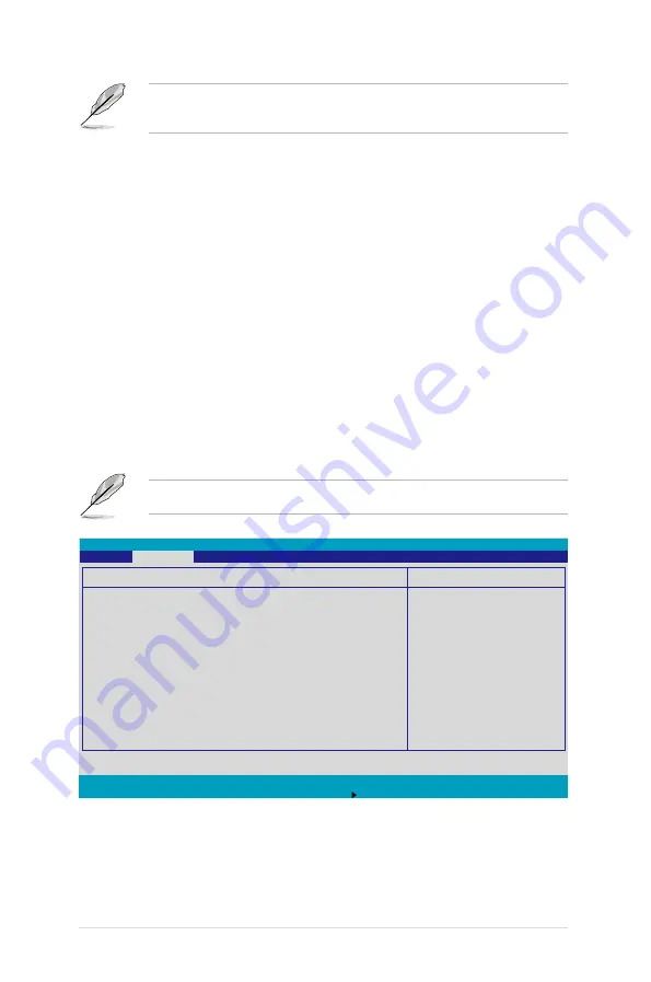
Item Specific Help

Full fan speed will 

be started when the 

temperature reaches the 

selected target value.

                   Hardware Monitor

  CPU1 Domain 0 Temperature  39

o

C/102

o

F

  CPU1 Domain 1 Temperature  29

o

C/84

o

F

  CPU2 Domain 0 Temperature  0

o

C/32

o

F

  CPU2 Domain 1 Temperature  0

o

C/32

o

F

  SYSTEM1 Temperature 


39

o

C/102

o

F

  SYSTEM2 Temperature 


29

o

C/84

o

F

  CPU_FAN1 Speed 


2925 RPM

  CPU_FAN2 Speed 


N/A

  FRN_FAN1 Speed 


N/A

  FRN_FAN2 Speed 


N/A

  FRN_FAN3 Speed 


N/A

  FRN_FAN4 Speed 


N/A

  REAR_FAN1 Speed 


N/A

  REAR_FAN2 Speed 


N/A

  Smart Fan Control 


[Smart Fan II]

PhoenixBIOS Setup Utility


Advanced

5.4.8 Hardware Monitor

This menu shows the hardware monitor configuration settings.  Select an 

item then press <Enter> to display the configuration options.

The following screens appear when you install Intel

®

 5000 series CPU.

Summary of Contents for Pedestal/5U Rackmount Server TS500-E4 Server

Page 1: ...TS500 E4 Server Pedestal 5U Rackmount Server User s Manual ...

Page 2: ... of business and the like even if ASUS has been advised of the possibility of such damages arising from any defect or error in this manual or product Specifications and information contained in this manual ae furnished for informational use only and are subject to change at any time without notice and should not be construed as a commitment by ASUS ASUS assumes no responsibility or liability for a...

Page 3: ...are setup 2 1 Chassis cover 2 2 2 1 1 Removing the side cover 2 2 2 1 2 Reinstalling the side cover 2 3 2 2 Motherboard information 2 4 2 3 Central Processing Unit CPU 2 5 2 3 1 Installing the CPU 2 5 2 3 2 Installing the CPU heatsink and fan 2 8 2 4 System memory 2 10 2 4 1 Overview 2 10 2 4 2 Memory configurations 2 10 2 4 3 Installing a DIMM 2 12 2 4 4 Removing a DIMM 2 12 2 5 Front panel assem...

Page 4: ...t 2 38 2 10 5 Floppy disk drive 2 41 2 10 6 Front I O board 2 43 2 10 7 Chassis footpads and roller wheels 2 45 2 10 8 Power supply unit 2 47 3 Chapter 3 Installation options 3 1 Preparing the system for rack mounting 3 2 3 1 1 Removing the footpads or roller wheels 3 2 3 1 2 Removing the top cover 3 2 3 1 3 Attaching the rack rails 3 2 3 2 Installing ASUS certified CPU heatsink and fan assembly 3...

Page 5: ... xx 5 13 5 3 3 Floppy A 1 44M 3 5 in 5 13 5 3 4 IDE Configuration 5 14 5 3 5 IDE Channel 0 Master Slave SATA Port 1 2 3 4 5 16 5 3 6 System Information 5 17 5 4 Advanced menu 5 19 5 4 1 Advanced Processor Options 5 19 5 4 2 Chipset Configuration 5 21 5 4 3 PCI Configuration 5 23 5 4 4 ICH USB Control Sub Menu 5 25 5 4 5 Peripheral Devices Configuration 5 26 5 4 6 ACPI Configuration 5 28 5 4 7 Powe...

Page 6: ...on 6 28 6 2 8 Selecting the boot drive from a RAID set 6 29 6 2 9 Enabling the WriteCache 6 30 6 3 Intel Matrix Storage Manage Option ROM Utility Only for PA4 model 6 31 6 3 1 Creating a RAID 0 set Stripe 6 32 6 3 2 Creating a RAID 1 set Mirror 6 34 6 3 3 Creating a RAID 10 set Stripe Mirror 6 35 6 3 4 Creating a RAID 5 set Parity 6 36 6 3 5 Deleting a RAID set 6 37 6 3 6 Resetting disks to Non RA...

Page 7: ...vii 7 3 1 Windows 2000 Server 2003 7 17 Appendix Reference information A 1 670 W single power supply A 2 A 1 1 General description A 2 A 1 2 Specifications A 3 A 2 Simple fixes A 4 ...

Page 8: ...e harmful interference to radio or television reception which can be determined by turning the equipment off and on the user is encouraged to try to correct the interference by one or more of the following measures Reorient or relocate the receiving antenna Increase the separation between the equipment and receiver Connect the equipment to an outlet on a circuit different from that to which the re...

Page 9: ...erver carefully read all the manuals included with the server package Before using the server make sure all cables are correctly connected and the power cables are not damaged If any damage is detected contact your dealer as soon as possible To avoid short circuits keep paper clips screws and staples away from connectors slots sockets and circuitry Avoid dust humidity and temperature extremes Plac...

Page 10: ...ormation This chapter gives information about the motherboard that comes with the server This chapter includes the motherboard layout jumper settings and connector locations 5 Chapter 5 BIOS information This chapter tells how to change system settings through the BIOS Setup menus and describes the BIOS parameters 6 Chapter 6 RAID configuration This chapter provides information on how toconfigure y...

Page 11: ...on to prevent damage to the components when trying to complete a task IMPORTANT Instructions that you MUST follow to complete a task NOTE Tips and information to aid in completing a task References Refer to the following sources for additional information and for product and software updates 1 ASUS Server Web based Management ASWM user guide This manual tells how to set up and use the proprietary ...

Page 12: ...xii ...

Page 13: ...This chapter describes the general features of the chassis kit It includes sections on front panel and rear panel specifications Chapter 1 Product introduction ...

Page 14: ...trol card SATA Cable 4 pcs SAS Cable 1 pcs CD ROM or DVD ROM drive Floppy disk drive Chassis fan HDD blower MemCool FB DIMM fan kit Hot swap HDD trays including HDD screws Chassis roller wheels 4 sets Front I O board SMBus cable Dummy Covers 2 pcs Parallel port cable 1 pcs 2 AC power cable 3 System screws and cables 4 System keys 2 pcs 5 Bundled CDs TS500 E4 support CD with ASWM Computer Associate...

Page 15: ... memory LAN 2 x Gigabit LAN Intel 82563EB PCI E Gigabit LAN controller VGA ATI ES1000 VGA controller Supports 32MB display memory Storage 4 x Hot Swap SATA2 PA4 PX4 Model SAS PX4 Model Only HDDs bay 3 x 5 25 Drive bay 1 x 1 44MB FDD bay RAID Intel 6321ESB ICH controller supports PA4 Model Only Intel Matrix Storage Windows support RAID 0 RAID 1 RAID 0 1 RAID5 S W LSI MegaRAID Linux Windows support ...

Page 16: ...nnector Management ASUS Server Web based Management ASWM Hardware support SM Bus ASMB3 supports IMIP 2 0 LAN management card Hardware monitors Voltage temperature and fan speed monitoring Automatic System Restart ASR feature Power supply 670W single power supply 100V 240V 50Hz 60Hz Dimensions 431mm H x 220mm W x 510mm D Specifications are subject to change without notice ...

Page 17: ...bays power and reset buttons LED indicators optical drive floppy drive and USB 2 0 ports are located on the front panel For future installation of 5 25 inch devices two drive bays are available Optical drive Empty 5 25 inch bays Power button Reset button Message LED HDD access LED Power LED Floppy disk drive USB 2 0 ports HDD bays Security lock ...

Page 18: ...r the motherboard rear I O ports expansion slots a chassis lock and intrusion switch a vent for the system fan and power supply module Power connector 12 cm system fan Gigabit LAN ports VGA port Serial port USB 2 0 ports PS 2 keyboard port Power supply module Expansion slots PS 2 mouse port ...

Page 19: ...S500 E4 with the disk blower installed 1 Power supply unit 2 Chassis fan 3 ASUS DSBV D Motherboard 4 Chassis intrusion switch 5 Expansion card locks 6 Optical drive 7 2 x5 25 inch drive bays 8 HDD blower HDD drive cage inside 9 SATA2 backplane PA4 Model Only 10 Front I O board 2 8 7 9 1 3 10 5 4 6 PA4 4 hot swap SATA configuration ...

Page 20: ...S DSBV D Motherboard 4 Chassis intrusion switch 5 Expansion card locks 6 Optical drive 7 2 x5 25 inch drive bays 8 HDD blower HDD drive cage inside 9 SAS backplane PX4 Model Only 10 Front I O board 11 SAS control card 2 8 7 9 1 3 10 5 4 6 PX4 4 hot swap SAS configuration 11 ...

Page 21: ...rmal no incoming event ASWM detects a HW monitor event Hard disk drives Drive Status LED Green Red Green Red Blinking Bridge board connected to backplane Installed HDD is in good condition HDD failure PX4 model only HDD rebuilding using the RAID card PX4 model only Drive Activity LED Blinking Read write data into the HDD PX4 model only 1 6 1 Front panel LEDs Drive Status LED green red Drive Activi...

Page 22: ...Rear panel LEDs ACT LINK LED SPEED LED Status Description Status Description OFF No link OFF 10Mbps connection Green Linked Orange 100Mbps connection Blinking Data activity Green 1000Mbps connection SPEED LED ACT LINK LED SPEED LED ACT LINK LED ...

Page 23: ...ASUS TS500 E4 2 This chapter lists the hardware setup proce dures that you have to perform when install ing or removing system components Chapter 2 Hardware setup ...

Page 24: ...f an inch toward the rear until it is disengaged from the chassis 3 Carefully lift the cover and set it aside Viewing the internal structure Without the side cover the internal structure and installed components of the barebone server vary depending on the model you purchased Refer to section 1 5 Internal features for the different model configurations Perform the procedures in the succeeding sect...

Page 25: ...r to the corresponding chassis holes and edge 2 Slide the cover toward the front until it snaps in place You may need to remove some of the installed components to access the DIMM sockets and internal connectors Refer to section 2 10 Removable components for instructions 3 Drive in the two screws you removed earlier to secure the side cover 2 3 3 ...

Page 26: ... 6 screws as indicated by the circles in the illustration below Make sure to unplug the chassis power cord before installing or removing the motherboard Failure to do so can cause you physical injury and dam age motherboard components Place this side towards the rear of the chassis DSBV D Refer to Chapter 4 Motherboard information for detailed information on the motherboard ...

Page 27: ...n follow the latter Upon purchase of the motherboard make sure that the PnP cap is on the socket and the socket contacts are not bent Contact your retailer immediately if the PnP cap is missing or if you see any damage to the PnP cap socket contacts motherboard components ASUS will shoulder the cost of repair only if the damage is shipment transit related Keep the cap after installing the motherbo...

Page 28: ...emove the PnP cap un less you are installing a CPU 3 Lift the load lever in the direction of the arrow to a 135º angle 4 Lift the load plate with your thumb and forefinger to a 100º angle A then push the PnP cap from the load plate window to remove B 5 Position the CPU over the socket making sure that the gold triangle is on the bottom left corner of the socket The socket alignment key should fit ...

Page 29: ...er Threading compiler to compile the code If you are using any other operating systems disable the Hyper Threading Technology item in the BIOS to ensure system stability and performance Installing Windows 2003 Server or later version is recommended Make sure to enable the Hyper Threading Technology item in BIOS before installing a supported operating system For more information on Hyper Threading ...

Page 30: ...installing the heatsink and fan Refer to the installation manual that came with the CPU package for details on heatsink fan assembly and installation For installation instruction of optional ASUS qualified CPU heatsink and fan assembly refer to section 3 2 To install the CPU heatsink and fan 1 Place the heatsink on top of the installed CPU making sure that the four screws on the heatsink align wit...

Page 31: ...tor 2 Use a Phillips screwdriver to tighten the four heatsink screws in a diagonal sequence 3 Connect the fan cable to the 4 pin connector labeled CPU_FAN1 4 Repeat steps 1 to 3 to install the other heatsink if you have installed a second CPU then connect the fan cable to the 4 pin connector labeled CPU_FAN2 CPU_FAN1 connector ...

Page 32: ...MM sockets 2 4 2 Memory configurations You may install 256 MB 512 MB 1 GB 2 GB and 4 GB registered ECC FB DIMMs into the DIMM sockets For optimum compatibility we recommend that you obtain memory modules from the same vendor Refer to the Qualified Vendors List on the ASUS web site This motherboard does not support memory modules made up of 128 Mb chips or double rank x16 memory modules If you are ...

Page 33: ...e DIMMs in pair means two DIMMs with the same configuration For better performance same configuration DIMMs should be installed on the same slot number for each channel For example you may install the same type of DIMMs in DIMM_00 and DIMM_10 No of DIMMs Slot s to use 1 DIMM_00 2 DIMM_00 DIMM_10 4 DIMM_00 DIMM_01 DIMM_10 DIMM_11 6 DIMM_00 DIMM_01 DIMM_02 DIMM_10 DIMM_11 DIMM_12 ...

Page 34: ...d the DIMM is properly seated 2 4 4 Removing a DIMM To remove a DIMM 1 Simultaneously press the retaining clips outward to unlock the DIMM 2 Remove the DIMM from the socket A FB DIMM is keyed with a notch so that it fits in only one direction Do not force a DIMM into a socket to avoid damaging the DIMM The sockets do not support DDR DDR2 DIMMs DO NOT install DDR DDR2 DIMMs to the FB DIMM sockets S...

Page 35: ... to the chassis through three hooked tabs on the left side and four hinge like tabs on the right side To remove the front panel assembly 1 Locate the four hooked tabs on the chassis side rail 2 Press each lock tab to release the front panel from the chassis 2 5 Front panel assembly 2 5 1 Removing the front panel assembly 3 Pull and swing the left edge of the front panel outward ...

Page 36: ... 14 Do not use too much force when removing the front panel assembly 4 Unhook the hinge like tabs from the holes on the right side of the front panel to completely detach the front panel assembly from the chassis Hinge like tab ...

Page 37: ... panel assembly front bezel and front panel cover 1 Insert the four hinge like tabs to the holes on the right edge of the chassis 2 Swing the front panel to the left and fit the four 4 hooked tabs to the left side of the chassis until the tabs snap back in place Hinge like tab 1 1 1 1 2 ...

Page 38: ...devices If you have previously used and powered up the system and that it may be connected to an AC power source make sure to unplug the power cable before installing or removing any system components Failure to do so may cause damage to the motherboard and other system compo nents To install a 5 25 inch drive 1 Use a Phillips cross screwdriver to remove the screws that secure the metal cover of t...

Page 39: ... the drive 6 Connect a 4 pin plug from the power supply to the power connector on the back of the drive IDE cable Power plug 3 Make sure that the drive and bay hole align as shown When in place the drive protrudes about an inch from the front panel 4 Secure the drive with a screw ...

Page 40: ...etach the plastic bay cover opposite the 5 25 inch drive that you installed by pressing the two hooked tabs on each side of the bay cover 8 Reinstall the front panel assembly when done Refer to section 2 5 2 Reinstalling the front panel assembly for instructions ...

Page 41: ...rive trays 2 Release a drive tray by pushing the spring lock to the right then pulling the tray lever outward The drive tray ejects slightly after you pull out the lever 3 Firmly hold the tray lever and pull the drive tray out of the bay 4 An empty drive tray requires a metal bracket for support Use a Phillips cross screwdriver to remove the bracket when you are ready to install a hard disk in the...

Page 42: ... four screws 6 Carefully insert drive tray and push it all the way to the depth of the bay until just a small fraction of the tray edge protrudes 7 Push the tray lever until it clicks and secures the drive tray in place The drive tray is correctly placed when its front edge aligns with the bay edge ...

Page 43: ... HDD dummy cover The HDD dummy covers come pre installed on the front panel bezel In case you removed the covers follow these steps to re install them To install an HDD dummy cover 1 From the inside of the front panel assembly insert the flat end of a dummy cover into the slot as shown The end with the hook tab should be close to the front panel LEDs Flat end Hook tab ...

Page 44: ...lling an expansion card To install an expansion card 1 Lay the chassis on its side 2 Locate the metal bracket opposite the slot you want to use Remove the screw that secures the metal bracket to the chassis Set aside the metal bracket for future use 3 Align the card golden fingers to the slot and its metal bracket to the slot opening on the chassis 4 Press the card firmly until it is properly seat...

Page 45: ...expansion card To remove an expansion card 1 Remove the screw that secures the card to the chassis 2 Carefully remove the card from the slot 3 Reinstall the metal bracket and secure it to the chassis with the screw that you removed earlier ...

Page 46: ...B1 USB2 RJ 45 LAN1 ATX12V1 CPU_FAN1 Intel 6321ESB PSUSMB1 BPSMB1 AUX_PANEL1 HDLED1 USB34 USBPW34 LAN_BW1 LPT1 USBPW12 DSBV D ASMB3 Intel 5000V PCIE1 FB DIMM_00 64 72 bit 240 pin module 26 7cm 10 5in 30 5cm 12in COM1 VGA1 PCIE2 PCIX5 PCIX4 PCI3 PCIX6 REAR_FAN2 ATX12V2 PRI_IDE1 FRNT_FAN2 SATA2 SATA1 SGIOP1 RECOVERY1 VGA_EN1 LAN_EN1 DIP_SW1 RJ 45 LAN2 FB DIMM_01 64 72 bit 240 pin module FB DIMM_02 64...

Page 47: ...the front panel LEDs to indicate HDD status See section 1 6 LED information for details Front side The front side of the SATA backplane faces the front panel when installed This side includes four SATA connectors for the hot swap drive trays Drive status LEDs CON1 CON3 CON5 CON7 Each SATA connector is labeled CON1 CON3 CON5 CON7 so you can easily determine their counterpart connectors at the back ...

Page 48: ...AN1 RAID_SEL1 SATA4 SATA3 SATA6 SATA5 Intel 82563EB 12V4LED1 SB_PWR1 Back side The back side of SATA backplane faces the rear panel when installed This side includes the power connectors SATA interfaces for the motherboard Serial ATA connectors or the SATA RAID card an HDD fan connector and SMBus connectors Fan connector for HDD fan Power connectors connect power plugs from the power supply The ba...

Page 49: ... your desired SATA configuration The picture below shows the location of jumper J3 with pins 1 3 and 2 4 shorted Refer to the table for the jumper settings and the appropriate ID for each SATA HDD bay J3 setting 1 3 shorted 2 4 shorted Device SATA ID Drive Bay 1 ID0 Drive Bay 2 ID1 Drive Bay 3 ID2 Drive Bay 4 ID3 ...

Page 50: ...wap feature to allow easy connection or removal of SAS hard disks The LEDs on the backplane connect to the front panel LEDs to indicate HDD access HDD failure thermal failure or fan failure See section 1 6 LED information Front side The front side of the SAS backplane faces the front panel when installed This side includes four SAS connectors for the hot swap drive trays HDD status LEDs HDD activi...

Page 51: ...d an HDD fan con nector and SMBus connectors the SAS interface of the backplane connects to a SAS RAID card SMBus connector J2 connects the SMB cable from the motherboard Fan connector for HDD fan Power connectors connect power plugs from the power supply SAS connector connect to SAS RAID card Select Address as default Select Address You do not have to change these jumpers Please keep the jumpers ...

Page 52: ...l card 2 Then connect another side of the SAS cable to the SAS backplane 3 The picture shows the SAS backplane connects to SAS control card For more detailed instruction about the SAS RAID card refer to its user guide The pictures of the SAS RAID card above illustrate the LSI SAS3442X R card only ...

Page 53: ...eplace defective components This section tells how to remove the following components 1 Chassis fan 2 HDD blowers 3 SATA SAS backplanes 4 MemCool FB DIMM fan kit 5 Floppy disk drive module 6 Front I O board 7 Chassis footpads and roller wheels 8 Power supply unit 2 Locate the four screws that secure the fan to the chassis 3 Remove the four screws while carefully supporting the chassis fan with you...

Page 54: ...ive in the four screws you removed earlier to secure the fan to the chassis 5 Remove the four screws that secure the metal shroud to the fan Set the screws aside To reinstall the chassis fan 1 Drive in the four screws you removed earlier into the fan screw holes to secure the metal shroud to the fan ...

Page 55: ...ct the 3 pin fan cable from the fan connector on the backplane 4 Firmly grip the blower case as shown then slide it out of the chassis in the direction of the arrow until the tabs are released from the holes of the HDD cage 3 Loosen the thumb screw that secures the HDD blower case to the chassis 3 Plug the chassis fan cable to the connector on the motherboard ...

Page 56: ...ower from the case To reinstall the HDD blower 1 Replace the blower into the case 2 Secure the blower to the case with the two screws you removed earlier 5 Remove the two screws on the blower case using a Phillips screwdriver Set the screws aside ...

Page 57: ...4 4 Drive in the thumb screw to secure the HDD blower case 5 Connect the 3 pin fan cable to the fan connector on the backplane 3 Slide in the blower case as shown making sure the tabs fit into the holes on the HDD cage ...

Page 58: ...tructions 2 Disconnect all cables from the SATA SAS backplane When disconnecting a cable hold and firmly pull the cable plug DO NOT pull the cable itself Doing so may damage the cable 3 From the inner edge push the backplane outward so that the outer edge protrudes slightly from the slot 4 From the outer edge firmly hold the backplane and carefully slide it out ...

Page 59: ...kplane with the rail like dents on the slot to ensure that it fits securely 3 Slide the backplane into the slot until it fits If correctly installed the outer edge of the backplane aligns with the corner of the drive cage 4 Connect the appropriate cables to the backplane Refer to sections 2 9 2 SATA backplane connections and 2 9 3 SAS backplane connections for details Rail like dents ...

Page 60: ...ion and perfor mance 2 10 4 MemCool FB DIMM fan kit To remove the MemCool FB DIMM fan kit 1 Unplug the fan cable from the FBD_FAN1 connector on the motherboard 2 Grip the top cover clamps until the top cover hooks are released then carefully lift the top cover while supporting the fan base with your free hand Top cover clamp 3 Carefully lift the fan base ...

Page 61: ...ates from the fan base Do not remove the fan from the fan base 3 Position the fan base over the DIMMs and insert the fan base legs into the FB DIMM holes until the legs are securely in place For instructional purposes only no FB DIMM is installed on any of the slots Top cover hook Fan base Top cover clamp To reinstall the MemCool FB DIMM fan kit 1 Locate the three FB DIMM fan holes on the motherbo...

Page 62: ...r labeled FBD_FAN1 4 Position top cover over the fan base Insert the top cover legs into the slot on the fan base legs Push down carefully until the legs are securely in place and the top cover hooks snap in place Make sure the cables pass through the notch on the fan base as shown ...

Page 63: ...remove the floppy disk drive 1 Remove the screw that secures the drive to the chassis You need to remove the front panel assembly before you can remove the floppy disk drive Refer to section 2 5 1 Removing the front panel assembly for instructions 3 Disconnect the floppy disk cable and power cable from the drive to completely release the drive ...

Page 64: ...ct button on the left side close to the HDDs 2 Connect the drive signal cable and power cable 4 Secure the drive cage with a screw 3 Carefully push the drive into the bay until the drive cage fits the front edge of the bay Floppy drive power cable Floppy drive signal cable Red stripe to match Pin 1 on the connector ...

Page 65: ...Removing the front panel assembly for instructions To remove the front I O board 1 Remove the screw that secures the front I O board bracket to the front panel 4 Remove the screw that secures the I O board to the bracket 2 Carefully pull out the bracket until you see the cables connected to the I O board 3 Disconnect all the cables from the I O board ...

Page 66: ...oard to the bracket with a screw 2 Position the I O board into the bay with the component side to the left close to the HDDs Connect the I O cables to the connectors on the back of the I O board 3 Insert the I O board into the bay until the bracket fits the front edge of the bay 4 Secure the I O board bracket with a screw USB 2 0 connector ...

Page 67: ...the footpads with the bundled roller wheels you wish to install the system to a rack Refer to Chapter 3 Installation options of this user guide and to the Rackmount Kit user guide for instructions To remove the footpads 1 Lay the system chassis on its side 2 Use a flat screwdriver to flip out the top layer of a footpad 4 Repeat steps 2 and 3 to remove the other three footpads 3 Remove the footpad ...

Page 68: ...to mount the system to a rack For convenient transport install the roller wheels the came with the system package Each wheel has a brake lock to stabilize the chassis in place To install the chassis wheels 1 Lay the chassis in its side 2 Locate the designated screw holes for each of the four wheel sets Take note of the numbers alongside each hole when placing screws 3 Secure each wheel to the bott...

Page 69: ...2 1 3 Model PA4 1 24 pin ATX motherboard power connector 2 4 pin 12V motherboard power connector hidden behind the cables 3 8 pin 12V motherboard power 4 4 pin plug optical drive 5 2 x 4 pin plugs SATA backplane 6 4 pin plug floppy disk drive hidden behind the backplane Model PX4 1 24 pin ATX motherboard power connector 2 4 pin 12V motherboard power connector hidden behind the cables 3 8 pin 12V m...

Page 70: ...n 2 1 1 Removing the side cover 2 Lay the chassis on a flat stable surface 3 Locate the four screws on the rear panel Remove the screws and set them aside 4 Locate and remove the screws that secure the PSU bracket to the chassis 5 Slide the bracket in the direction of the arrow and remove it from the chassis ...

Page 71: ...the PSU in the direction of the arrow until it disengages from the chassis To reinstall the power supply unit 1 Carefully slide the PSU in the direction of the arrow 2 Secure the PSU to the chassis with the four screws you removed earlier ...

Page 72: ...Chapter 2 Hardware setup 2 50 3 Slide in the PSU bracket 4 Align the screw holes 5 Secure the bracket with screws you removed earlier ...

Page 73: ...3 ASUS TS500 E4 This chapter describes how to in stall optional components into the barebone server Chapter 3 Installation option ...

Page 74: ... the top cover To remove the top cover 1 Remove the chassis cover Refer to section 2 1 1 Removing the side cover 2 Remove the front panel assembly Refer to section 2 5 1 Removing the front panel assembly 3 Carefully slide out protruding portion of the top cover as shown 3 1 3 Attaching the rack rails Refer to the installation guide that came with the Rackmount Rail Kit for instructions on how to a...

Page 75: ...Philips screwdriver to tihghten the four heatsink screws in a diagonal sequence Do not forget to connect the CPU fan cable Hardware m o n i t o r i n g e r r o r s m a y occur if you fail to plug this connector 3 Connect the fan cable to the 4 pin connector labeled CPU_FAN1 4 Repeat steps 1 to 3 to install the other heatsink if you have installed a second CPU then connect the fan cable to the 4 pi...

Page 76: ...Chapter 3 Installation option 3 ...

Page 77: ...Chapter 4 Motherboard info This chapter gives information about the motherboard that comes with the server This chapter includes the motherboard layout jumper settings and connector locations ...

Page 78: ...ntel 5000V PCIE1 FB DIMM_00 64 72 bit 240 pin module 26 7cm 10 5in 30 5cm 12in COM1 VGA1 PCIE2 PCIX5 PCIX4 PCI3 PCIX6 REAR_FAN2 ATX12V2 PRI_IDE1 FRNT_FAN2 SATA2 SATA1 SGIOP1 RECOVERY1 VGA_EN1 LAN_EN1 DIP_SW1 RJ 45 LAN2 FB DIMM_01 64 72 bit 240 pin module FB DIMM_02 64 72 bit 240 pin module FB DIMM_10 64 72 bit 240 pin module FB DIMM_11 64 72 bit 240 pin module FB DIMM_12 64 72 bit 240 pin module C...

Page 79: ...slots 4 2 4 DDR2 SODIMM socket 4 2 5 PCI Express x8 slot 4 2 6 PCI Express x16 slot 4 2 Internal connectors Page 1 Floppy disk drive connector 34 1 pin FLOPPY1 4 10 2 IDE connectors 40 1 pin PRI_IDE 4 10 3 Serial ATA connectors 7 pin SATA1 SATA2 SATA3 SATA4 SATA5 SATA6 4 11 4 Hard disk activity LED connector 4 pin HDLED 4 11 5 USB connectors 10 1 pin USB34 4 12 6 Serial port connector 10 1 pin COM...

Page 80: ...onboard button cell battery powers the RAM data in CMOS which include system setup information such as system passwords To erase the RTC RAM 1 Turn OFF the computer and unplug the power cord 2 Remove the onboard battery 3 Move the jumper cap from pins 1 2 default to pins 2 3 Keep the cap on pins 2 3 for about 5 10 seconds then move the cap back to pins 1 2 4 Reinstall the battery 5 Plug the power ...

Page 81: ...e 5VSB lead for each USB port otherwise the system will not power up If you are using Windows 2000 you need to install Service Pack 4 to wake up the system from S4 sleep mode The total current consumed must NOT exceed the power supply capability 5VSB whether under normal condition or in sleep mode 2 LAN bandwidth setting 3 pin LAN_BW1 This jumper allows you to set the LAN bandwidth setting for mor...

Page 82: ...default is the Space Bar This feature requires an ATX power supply that can supply at least 1A on the 5VSB lead and a corresponding setting in the BIOS 5 VGA controller setting 3 pin VGA_EN1 These jumpers allow you to enable or disable the onboard VGA controller Set to pins 1 2 to activate the VGA feature DSBV D DSBV D Keyboard power setting KBPWR1 Default 5V 5VSB 3 2 2 1 DSBV D DSBV D VGA setting...

Page 83: ... Serial ATA RAID configuration utility to use when you create disk arrays Both utilities are supported by the Intel 6321ESB Place the jumper caps on pins 1 2 if you want to use the LSI MegaRAID Serial ATA RAID utility default otherwise place the jumper caps on pins 2 3 to use the Intel Matrix Storage Manager IMSM DSBV D DSBV D LAN1_EN setting LAN1_EN1 1 2 2 3 Enable Default Disable DSBV D DSBV D 6...

Page 84: ... update the BIOS 4 Shut down the system 5 Set the jumper back to pins 1 2 6 Turn on the system DSBV D DSBV D BIOS recovery setting RECOVERY1 Default Normal BIOS Recovery 1 2 2 3 DSBV D DSBV D DIP switches DIP_SW1 ON 4 PIN FAN OFF 3 PIN FAN SW1 CPU_FAN1 switch ON SW2 CPU_FAN2 switch ON SW3 FRNT_FAN1 switch OFF SW4 FRNT_FAN2 switch OFF SW5 FRNT_FAN3 switch OFF SW6 FRNT_FAN4 switch OFF SW7 REAR_FAN1 ...

Page 85: ...2 mouse 2 PS 2 keyboard port purple This port is for a PS 2 keyboard 3 USB 2 0 ports 1 and 2 These two 4 pin Universal Serial Bus USB ports are available for connecting USB 2 0 devices 4 Serial COM1 port This 9 pin communication port is for pointing devices or other serial devices 5 Video Graphics Adapter port This port is for a VGA monitor or other VGA compatible devices 6 LAN RJ 45 ports These p...

Page 86: ...loppy disk drive connector 34 1 pin FLOPPY1 This connector is for the provided floppy disk drive FDD signal cable Insert one end of the cable to this connector then connect the other end to the signal connector at the back of the floppy disk drive Pin 5 on the connector is removed to prevent incorrect cable connection when using a FDD cable with a covered Pin 5 Pin 20 on the IDE connector is remov...

Page 87: ...TA1 DSBV D SATA connectors SATA4 SATA3 SATA6 SATA5 GND RSATA_TXP1 RSATA_TXN1 GND RSATA_RXN1 RSATA_RXP1 GND GND RSATA_TXP2 RSATA_TXN2 GND RSATA_RXN2 RSATA_RXP2 GND GND RSATA_TXP3 RSATA_TXN3 GND RSATA_RXN3 RSATA_RXP3 GND GND RSATA_TXP4 RSATA_TXN4 GND RSATA_RXN4 RSATA_RXP4 GND GND RSATA_TXP5 RSATA_TXN5 GND RSATA_RXN5 RSATA_RXP5 GND GND RSATA_TXP6 RSATA_TXN6 GND RSATA_RXN6 RSATA_RXP6 GND DSBV D DSBV D...

Page 88: ...The serial port module is purchased separately 5 USB connector 10 1 pin USB34 This connector is for USB 2 0 ports Connect the USB cable to this connector and another USB connector on the front I O board This USB connector complies with USB 2 0 specification that supports up to 480 Mbps connection speed DSBV D DSBV D USB connector USB34 Power 1 USB PortA USB PortA GND Power USB PortB USB PortB GND ...

Page 89: ...onnectors 8 Power supply SMBus connector 5 pin PSUSMB1 This connector is for the power supply SMB cable if your power supply supports the SMBus function DSBV D DSBV D Fan connectors CPU_FAN1 CPU_FAN2 REAR_FAN1 REAR_FAN2 FRNT_FAN1 FRNT_FAN2 FRNT_FAN3 FRNT_FAN4 FBD_FAN1 CPU_FAN1 CPU_FAN2 GND FAN Power FAN Speed PWM Control GND FAN Power FAN Speed PWM Control REAR_FAN1 REAR_FAN2 GND FAN Power FAN Spe...

Page 90: ...t to connect the 24 8 4 pin power plugs otherwise the system will not boot up Use of a PSU with a higher power output is recommended when configuring a system with more power consuming devices The system may become unstable or may not boot up if the power is inadequate You must install a PSU with a higher power rating if you intend to install additional devices DSBV D DSBV D ATX power connectors 8...

Page 91: ...V D Parallel port connector LPT1 SPD7 GND SPD6 GND SPD5 GND SPD4 GND SLCT PE GND BUSY ACK GND SPD3 GND SPD2 SLIN SPD1 PINIT SPD0 ERROR STB AFD GND Pin 1 11 Backplane SMBus connector 7 1 pin BPSMB1 This connector allows you to connect SMBus System Management Bus devices Devices communicate with an SMBus host and or other SMBus devices using the SMBus interface DSBV D DSBV D BPSMB connector BPSMB1 1...

Page 92: ...rmation 12 Serial General Purpose Input Output connector 6 1 pin SGPIO1 This connector is used to the SGPIO peripherals for the LSI MegaRAID SATA LED DSBV D DSBV D SGPIO connector SGPIO1 1 GND SATA_SCLK SATA_SLOAD SDATAOUT1 SDATAOUT0 ...

Page 93: ...is read from or written to the HDD System warning speaker Orange 4 pin SPEAKER This 4 pin connector is for the chassis mounted system warning speaker The speaker allows you to hear system beeps and warnings ATX power button soft off button Yellow 2 pin PWRSW This connector is for the system power button Pressing the power button turns the system on or puts the system in sleep or soft off mode depe...

Page 94: ...ese leads are for the intrusion detection feature for chassis with intrusion sensor or microswitch When you remove any chassis component the sensor triggers and sends a high level signal to these leads to record a chassis intrusion event 4 Locator LED 6 pin LOCATOR These leads are for the locator switch and LED on the front panel 5 Locator LED 6 pin LOCATOR These leads are for the locator switch a...

Page 95: ...Chapter 5 BIOS information This chapter tells hoe to change the system settings through the BIOS Setup menus Detailed descriptions of the BIOS parameters are also provided ...

Page 96: ...loppy disk into the drive b At the DOS prompt type format A S then press Enter Windows XP environment a Insert a 1 44 MB floppy disk to the floppy disk drive b Click Start from the Windows desktop then select My Computer c Select the 3 1 2 Floppy Drive icon d Click File from the menu then select Format A Format 3 1 2 Floppy Disk window appears e Select Create an MS DOS startup disk from the format...

Page 97: ...IOS WPH Save the file to a floppy disk Make sure you copy the correct BIOS file for the specific model of your motherboard Save only the updated BIOS file in the floppy disk to avoid loading the wrong BIOS file 2 Copy the Phoenix Phlash16 phlash16 exe utility from the Software folder of the support CD to the floppy disk with the latest BIOS file 3 Boot the system in DOS mode using the bootable flo...

Page 98: ...Disk Also support AHCI C Create INTEL 6321 MATRIX STORAGE MANAGER for Windows 64 bit Driver Disk Also support AHCI D Create INTEL 6321 LSI MegaRAID for Win2k Driver Disk E Create INTEL 6321 LSI MegaRAID for WinXP Win2k3 32 bit Driver Disk F Create INTEL 6321 LSI MegaRAID for WinXP Win2k3 64 bit Driver Disk G Create the emergent BIOS Recovery diskette H ESB2 ASF firmware update Please choose A TO H...

Page 99: ...ash memory has been successfully programmed PRESS ANY KEY TO RESTART THE SYSTEM If the system does not restart TURN THE POWER OFF THEN ON Flash part SST49LF008A DeviceID 5a Mfr ID bf Ready to restart the system 00 00 00 1E DO NOT shut down or reset the system while updating the BIOS Doing so can cause system boot failure Phoenix Phlash16 Utility Version 1 6 1 9 Copyright c Phoenix Technologies Ltd...

Page 100: ...S file Download the latest BIOS file from the Internet Update the BIOS from an updated BIOS file Update the BIOS directly from the Internet and View the BIOS version information This utility is available in the support CD that comes with the motherboard package ASUS Update requires an Internet connection either through a network or an Internet Service Provider ISP Quit all Windows applications bef...

Page 101: ...g the BIOS through the Internet To update the BIOS through the Internet 1 Launch the ASUS Update utility from the Windows desktop by clicking Start Programs ASUS ASUSUpdate ASUSUpdate The ASUS Update main window appears 2 S e l e c t U p d a t e B I O S f r o m the Internet option from the drop down menu then click Next ...

Page 102: ...pdate BIOS from a file option from the drop down menu then click Next 4 From the FTP site select the BIOS version that you wish to download Click Next 5 Follow the screen instructions to complete the update process The ASUS Update utility is capable of updating itself through the Internet Always update the utility to avail all its features 3 Locate the BIOS file from the Open window then click Sav...

Page 103: ...ess Del during the Power On Self Test POST to enter the Setup utility otherwise POST continues with its test routines If you wish to enter Setup after POST restart the system by pressing Ctrl Alt Delete or by pressing the reset button on the system chassis You can also restart by turning the system off and then back on Do this last option only if the first two failed The Setup program is designed ...

Page 104: ...ress the right or left arrow key on the keyboard until the desired item is highlighted 5 2 1 BIOS menu screen F1 Help Select Item Change Values F9 Setup Defaults ESC Exit Select Menu Enter Select Sub Menu F10 Save and Exit PhoenixBIOS Setup Utility Main Advanced Server Security Boot Exit Item Specific Help Tab Shift Tab or Enter selects field System Date 04 19 2006 System Time 15 30 36 Floppy A 1 ...

Page 105: ...ghted when selected To change the value of a field select it then press Enter to display a list of options Refer to 5 2 7 Pop up window 5 2 3 Legend bar At the bottom of the Setup screen is a legend bar The keys in the legend bar allow you to navigate through the various setup menus The following table lists the keys found in the legend bar with their corresponding functions Navigation Key Functio...

Page 106: ...efaults ESC Exit Select Menu Enter Select Sub Menu F10 Save and Exit PhoenixBIOS Setup Utility Main Advanced Server Security Boot Exit Item Specific Help Tab Shift Tab or Enter selects field System Date 04 19 2006 System Time 15 30 36 Floppy A 1 44 1 25 MB 3 1 2 IDE Configuration IDE Channel 0 Master None IDE Channel 0 Slave None SATA Port 1 None SATA Port 2 None SATA Port 3 None SATA Port 4 None ...

Page 107: ... Kb 3 1 2 1 44 1 25 MB 3 1 2 2 88 MB 3 1 2 Refer to section 5 2 1 BIOS menu screen for information on the menu screen items and how to navigate through them F1 Help Select Item Change Values F9 Setup Defaults ESC Exit Select Menu Enter Select Sub Menu F10 Save and Exit PhoenixBIOS Setup Utility Main Advanced Server Security Boot Exit Item Specific Help Tab Shift Tab or Enter selects field System D...

Page 108: ...write access to the boot sector on the hard disk to protect against viruses The defaul setting Normal allows write access Configuration options Normal Write Protect S ATA Configuration F1 Help Select Item Change Values F9 Setup Defaults ESC Exit Select Menu Enter Select Sub Menu F10 Save and Exit PhoenixBIOS Setup Utility Main Item Specific Help Enable the PATA S ATA Configuration Parallel ATA Ena...

Page 109: ...2000 XP When you set this item to Compatible Mode Serial ATA and Parallel ATA devices are auto detected and placed in legacy mode Configuration options Compatible Enhanced The following items appear only if you set the SATA Controller Mode Option item to Enhanced SATA RAID Enable Disabled Allows you to enable or disable the Serial ATA RAID function Configuration options Disabled Enabled SATA AHCI ...

Page 110: ...Removable if your device is either a ZIP LS 120 or MO drive Select User to manually enter the parameters of the device Configuration options Auto User Other ATAPI IDE Removable CD ROM ATAPI Removable Except for 32 Bit I O item the following items become user configurable when the Type item is not set to Auto For items that have no sub menu you have to use for values changing Multi Sector Transfers...

Page 111: ...ions Disabled Mode 0 Mode 1 Mode 2 Mode 3 Mode 4 Mode 5 5 3 6 System Information This menu gives you an overview of the general system specifications The BIOS automatically detects the items in this menu F1 Help Select Item Change Values F9 Setup Defaults ESC Exit Select Menu Enter Select Sub Menu F10 Save and Exit PhoenixBIOS Setup Utility Main Item Specific Help The detailed information for CPUs...

Page 112: ...32 KB L2 4096 KB ID uCode 0F64h 02h Processor Information Displays the auto detected CPU specification F1 Help Select Item Change Values F9 Setup Defaults ESC Exit Select Menu Enter Select Sub Menu F10 Save and Exit PhoenixBIOS Setup Utility Main Item Specific Help All items on this menu cannot be modified in user mode If any items require changes please consult your system Supervisor System Memor...

Page 113: ...essor Specification 1 4 Frequency Ratio Default Hyperthreading Enabled Intel R Virtualization Technology Enabled Machine Checking Enabled Fast String Operations Enabled Compatible FPU Code Disabled Split Lock operations Enabled C1 Enhanced Mode Enabled No Execute Mode Mem Protection Enabled Adjacent Cache Line Prefetch Enabled Set Max Ext CPUID 3 Disabled Echo TPR Disabled PhoenixBIOS Setup Utilit...

Page 114: ...tions 1 1 1 4 Intel R Virtualization Technology Enabled Configuration options Disabled Enabled Machine Checking Enabled Configuration options Disabled Enabled Fast String Operations Enabled Configuration options Disabled Enabled Compatible FPU Code Disabled Configuration options Disabled Enabled Split Lock operations Enabled Configuration options Disabled Enabled C1 Enhanced Mode Enabled Allows yo...

Page 115: ...nabled Force ITK Config Clocking Disabled FBDIMM s Thermal Throttling Open Loop Open Loop Type Best Performan Environment Temperature 025 O C PhoenixBIOS Setup Utility Advanced Scroll down to display the following item F1 Help Select Item Change Values F9 Setup Defaults ESC Exit Select Menu Enter Select Sub Menu F10 Save and Exit Temperature Rise 025 O C FBDIMM S Air Flow 2 0 Echo TPR Disabled Con...

Page 116: ... disable the FBD configuration for ITK test suite Configuration options Disabled Enabled FBDIMM s Thermal Throttling Open Loop Allows you to disable or set the thermal throttling control Configuration options Open Loop Close Loop ASUS MemCool Fan Disabled Open Loop Type Best Performance Allows you to select the Open Loop Type Configuration options Best Performance Best Acoustic User Define Crystal...

Page 117: ...nfiguration settings Select an item then press Enter to display the configuration options Reset Configuration Data No This item allows you to clear the Extended System Configuration Data ESCD area Configuration options No Yes Plug Play O S No When set to No BIOS configures all the devices in the system When set to Yes and if you install a Plug and Play operating system the operating system configu...

Page 118: ...ave and Exit Item Specific Help Initialize device expansion ROM PCI Device Slot 1 Optional ROM Scan Enabled PhoenixBIOS Setup Utility Advanced Optional ROM Scan Enabled Allows you to enable or disable the device expansion ROM Configuration options Enabled Disabled PCI Device Slot 1 6 Allows you to configure the specific PCI devices ...

Page 119: ...controller Configuration options Disabled Enabled The following items appear only if you enable the USB Function item USB 2 0 Controller Enabled Allows you to enable or disable the USB 2 0 controller Setting this item to Enabled allows the built in high speed USB support in the BIOS to turn on automatically when you install high speed USB devices Configuration options Disabled Enabled Legacy USB S...

Page 120: ...up Utility Advanced 5 4 5 Peripheral Devices Configuration This menu shows the peripheral devices configuration settings Select an item then press Enter to display the configuration options COM1 Port Enabled Allows you to configure serial port A Configuration options Disabled Enabled Auto Base I O address 3F8 Allows you to select the base I O address for serial port A Configuration options 3F8 2F8...

Page 121: ...parallel port Configuration options 378 278 3BC Interrupt IRQ 7 Allows you to set the interrupt for the parallel port Configuration options IRQ 5 IRQ 7 Mode ECP Allows you to set the mode for the parallel port Configuration options Output only Bi directional EPP ECP DMA channel DMA 3 Allows you to set the DMA channel for the parallel port Configuration options DMA 1 DMA 3 Floppy disk controller En...

Page 122: ...uration This menu shows the Advanced Configuration and Power Interface ACPI configuration settings Select an item then press Enter to display the configuration options ACPI Version Features ACPI v1 0 Allows you to enable RSDP pointers to 64 bit fixed system description tables Configuration options ACPI v1 0 ACPI v2 0 ACPI v3 0 Headless Mode Disabled Allows you to enable or disable the headless ope...

Page 123: ... after a power interruption When set to Last State the system goes into whatever was the system state on or off before the power interruption Configuration options Power Off Power On Last State Power Up By PS 2 Keyboard Disabled Allows you to use specific keys on the PS 2 keyboard to turn on the system This feature requires an ATX power supply that provides at least 1A on the 5VSB lead Configurati...

Page 124: ...nter Select Sub Menu F10 Save and Exit Item Specific Help Full fan speed will be started when the temperature reaches the selected target value Hardware Monitor CPU1 Domain 0 Temperature 39o C 102o F CPU1 Domain 1 Temperature 29o C 84o F CPU2 Domain 0 Temperature 0o C 32o F CPU2 Domain 1 Temperature 0o C 32o F SYSTEM1 Temperature 39o C 102o F SYSTEM2 Temperature 29o C 84o F CPU_FAN1 Speed 2925 RPM...

Page 125: ... V 1 8V 1 79 V 3V 3 28 V 12V 11 91 V 5V 4 87 V 5VSB 4 96 V VBAT 3 10 V PhoenixBIOS Setup Utility Advanced The following screens appear when you install Intel 5100 series CPU F1 Help Select Item Change Values F9 Setup Defaults ESC Exit Select Menu Enter Select Sub Menu F10 Save and Exit Item Specific Help Full fan speed will be started when the temperature reaches the selected target value Hardware...

Page 126: ...YSTEM1 2 Temperature C P U _ F A N 1 2 S p e e d F R N _ F A N 1 2 3 4 S p e e d REAR_FAN1 2 Speed These fields show the auto detected values and are not user configurable If no fan is installed the field shows 0 RPM Smart Fan Control Smart Fan II Allows you to disable or configure the Smart Fan feature Configuration options Disabled Smart Fan Smart Fan II CPU1 2 Domain 0 1 Target Temperature CPU1...

Page 127: ...s Server menu items allow you to customize the server features F1 Help Select Item Change Values F9 Setup Defaults ESC Exit Select Menu Enter Select Sub Menu F10 Save and Exit Item Specific Help If enabled it will use a port on the motherboard Console Redirection Com Port Address Disabled PhoenixBIOS Setup Utility Main Advanced Server Security Boot Exit 5 5 1 Console Redirection Com Port Address D...

Page 128: ... redirection Configuration options None XON XOFF CTS RTS Console connection Direct Allows you to select the console connection Direct indicates that the console is connected directed to the system Via modem indicates that a modem is used to connect Configuration options Direct Via modem Continue C R after POST Off Set this item to On if you want console redirection to continue after the operating ...

Page 129: ...rver Security Boot Exit 5 5 2 DMI Event Logging Event log validity Event log capacity Displays the auto detected system information View DMI event log Enter Press Enter to view the contents ofthe DMI event log Event Logging Enabled Enables or disables to allows logging of DMI events Configuration options Disabled Enabled ECC Event Logging Enabled Enables or disables to allows logging of ECC events...

Page 130: ...ted confirm the password by typing the exact characters again then press Enter The password field setting is changed to Set To clear the password 1 Select the item Set Supervisor Password or Set User Password depending on which password you want to clear Press Enter The following message appears PhoenixBIOS Setup Utility Main Advanced Server Security Boot Exit F1 Help Select Item Change Values F9 ...

Page 131: ... RTC RAM The RAM data containing the password information is powered by the onboard button cell battery If you need to erase the CMOS RAM refer to section 4 2 Jumpers for instructions Password Check Setup This field requires you to enter the password before entering the BIOS setup or the system Select Setup to require the password before entering the BIOS Setup Select System to require the passwor...

Page 132: ...lect a device and moves the device up or down f and r specifies the device as fixed or removable x excludes or includes the device to boot Shift 1 enables or disables the device 1 4 Loads default boot sequence Boot Device Priority Boot priority order 1 Legacy floppy drives 2 IDE 3 XXXX drive 3 4 5 6 7 8 Excluded from boot order PhoenixBIOS Setup Utility Main Advanced Server Security Boot Exit 5 7 ...

Page 133: ... tests POST while booting to decrease the time needed to boot the system When set to Disabled BIOS performs all the POST items Configuration options Disabled Enabled Full Logo Display Enabled Allows you to enable or disable the full screen logo display feature Configuration options Disabled Enabled Bootup Num Lock On Allows you to select the power on state for the NumLock Configuration options Aut...

Page 134: ...ges and Exit Discard Changes Load Setup Defaults 5 8 Exit menu PhoenixBIOS Setup Utility Main Advanced Server Security Boot Exit Save Changes and Exit Select this option then press Enter or simply press F10 to save your changes to CMOS before exiting the Setup utility When a confirmation window appears select Yes then press Enter to save and exit select No then press Enter or simply press Esc to c...

Page 135: ...usly saved values select No then press Enter or simply press Esc to cancel the command and return to the Exit menu Load Setup Defaults Select this option then press Enter or simply press F9 to load the optimized values for each of the Setup menu items When a confirmation window appears select Yes then press Enter to load the default values select No then press Enter or simply press Esc to cancel t...

Page 136: ...5 42 Chapter 5 BIOS information ...

Page 137: ...Chapter 6 RAID Configuration This chapter provides instructions for setting up creating and configuring RAID sets using the available utilities ...

Page 138: ...or this setup RAID 1 Data mirroring copies and maintains an identical image of data from one drive to a second drive If one drive fails the disk array management software directs all applications to the surviving drive as it contains a complete copy of the data in the other drive This RAID configuration provides data protection and increases fault tolerance to the entire system Use two new drives ...

Page 139: ...tached to the SATA connectors supported by the Intel 6321ESB Southbridge chip To do this 1 Enter the BIOS Setup during POST 2 Go to the Main Menu IDE Configuration S ATA Configuration then press Enter 3 Set the SATA Controller Mode Option item to Enhanced then press Enter 4 Set the SATA RAID Enable item to Enabled 5 Save your changes then exit the BIOS Setup Refer to Chapter 5 for details on enter...

Page 140: ...etup Utility Only for PA4 Model The LSI Logic Embedded SATA RAID Setup Utility allows you to create RAID 0 RAID 1 or RAID 10 set s from SATA hard disk drives connected to the SATA connectors supported by the motherboard Southbridge chip To enter the LSI Logic Embedded SATA RAID Setup Utility 1 Turn on the system after installing all the SATA hard disk drives 2 During POST the LSI Logic Embedded SA...

Page 141: ...data consistency of the logical drives of a created RAID set 6 2 1 Creating a RAID 0 or RAID 1 set The LSI Logic Embedded SATA RAID Setup Utility allows you to create a RAID 0 or RAID 1 set using two types of configurations Easy and New In Easy Configuration the logical drive parameters are set automatically including the size and stripe size RAID 1 only In New Configuration you manually set the l...

Page 142: ...SELECTION MENU displays the available drives connected to the SATA ports Select the drives you want to include in the RAID set then press SpaceBar When selected the drive indicator changes from READY to ONLIN A X Y where X is the array number and Y is the drive number The information of the selected hard disk drive displays at the bottom of the screen ...

Page 143: ...00 E4 6 5 Press F10 select the configurable array then press SpaceBar Press F10 again the logical drive information appears including a Logical Drive menu that allows you to change the logical drive parameters ...

Page 144: ...You need at least two identical hard disk drives when creating a RAID 1 set 8 When creating a RAID 1 set select DWC from the Logical Drive menu then press Enter When creating a RAID 0 set proceed to step 10 9 Select On to enable the Disk Write Cache setting then press Enter Enabling DWC can improve the performance but with the risk of data loss ...

Page 145: ...pt from the menu then press Enter 11 When finished setting the selected logical drive configuration select Accept from the menu then press Enter 12 Follow steps 5 to 10 to configure additional logical drives 13 When prompted save the configuration then press Esc to return to the Management Menu ...

Page 146: ... to view or create another RAID configuration To create a RAID set using the New Configuration option 1 From the utility main menu highlight Configure then press Enter 2 Use the arrow keys to select New Configuration then press Enter 3 Follow steps 3 to 7 of the previous section 4 Select Size from the Logical Drive menu then press Enter 5 Key in the desired logical drive size then press Enter 6 Fo...

Page 147: ... press Enter 2 Use the arrow keys to select Easy Configuration then press Enter 3 The ARRAY SELECTION MENU displays the available drives connected to the SATA ports Select the drive s you want to include in the RAID set then press SpaceBar When selected the drive indicator changes from READY to ONLIN A X Y where X is the array number and Y is The information of the selected hard disk drive display...

Page 148: ...12 Chapter 6 RAID configuration 4 Select all the drives required for the RAID 10 set then press Enter The configurable array appears on screen 5 Press F10 select the configurable array then press SpaceBar ...

Page 149: ...logical drive parameters 6 Select RAID from the Logical Drive menu then press Enter 7 Select RAID 10 from the menu then press Enter You need at least four identical hard disk drives when creating a RAID 10 set 8 Select DWC from the Logical Drive menu then press Enter 9 Select On to enable the Disk Write Cache setting then press Enter ...

Page 150: ...RAID configuration 10 When finished setting the selected logical drive configuration select Accept from the menu then press Enter 11 When prompted save the configuration then press Esc to return to the Management Menu ...

Page 151: ...hlight Configure then press Enter 2 Use the arrow keys to select View Add Configuration then press Enter 3 The ARRAY SELECTION MENU displays the available drives connected to the SATA ports Select the drive s you want to include in the RAID set then press SpaceBar When selected the drive indicator changes from READY to ONLIN A X Y where X is the array number and Y is the drive number The informati...

Page 152: ...or the RAID set then press Enter The configurable array appears on screen 5 Press F10 select the configurable array then press SpaceBar 6 Press F10 again and select RAID from the Logical Drive menu then press Enter 7 Select the RAID level from the menu then press Enter ...

Page 153: ...ating a RAID set Using Easy Configuration section 9 When prompted save the configuration then press Esc to return to the Management Menu 9 Follow steps 8 to 13 of the Creating a RAID set Using Easy Configuration section to add the new RAID configuration ...

Page 154: ...nitialize or Objects command on the Management Menu Using the Initialize command To initialize the logical drive using the Initialize command 1 From the Management Menu highlight Initialize then press Enter 2 The screen displays the available RAID set s and prompts you to select the logical drive to initialize Use the arrow keys to select the logical drive from the Logical Drive selection then pre...

Page 155: ...ct Yes from the Initialize dialog box then press Enter You may also press F10 to initialize the drive without confirmation Initializing a logical drive s erases all data on the drive 4 A progress bar appears on screen If desired press Esc to abort initialization ...

Page 156: ... 6 RAID configuration 5 When initialization is completed press Esc Using the Objects command To initialize the logical drives using the Objects command 1 From the Management Menu highlight Objects then press Enter ...

Page 157: ...Logical Drive from the Objects sub menu then press Enter 3 Select the logical drive to initialize from the Logical Drives sub menu then press Enter 4 Select Initialize from the pop up menu then press Enter to start initialization ...

Page 158: ...paceBar to select Yes from the Initialize dialog box then press Enter You may also press F10 to initialize the drive without confirmation 6 A progress bar appears on screen If desired press Esc to abort initialization 7 When initialization is completed press Esc ...

Page 159: ... using the Rebuild command in the Management Menu To rebuild a failed hard disk drive 1 From the Management Menu highlight Rebuild then press Enter 2 The PHYSICAL DRIVES SELECTION MENU displays the available drives connected to the SATA ports Select the drive you want to rebuild then press SpaceBar ...

Page 160: ...ID configuration 3 After selecting the drive to rebuild press F10 The indicator for the selected drive now shows RBLD 4 When prompted press Y to to rebuild the drive 5 When rebuild is complete press any key to continue ...

Page 161: ...tion in the Objects Adapter menu The Check Consistency command is available only for logical drives included in a RAID 1 set Using the Check Consistency To check data consistency using the Check Consistency command 1 From the Management Menu select Check Consistency then press Enter 2 The screen displays the available RAID set s and prompts you to select the logical drive to check Use the arrow ke...

Page 162: ...ng the disk consistency press Esc to display the following options Stop Stops the consistency check The utility stores the percentage of disk checked When you restart checking it continues from the last percentage completed rather than from zero percent Continue Continues the consistency check Abort Aborts the consistency check When you restart checking it continues from zero percent 5 When checki...

Page 163: ...ement Menu select Objects then select Logical Drive from the menu 2 Use the arrow keys to select the logical drive you want to check then press Enter 3 Select Check Consistency from the pop up menu then press Enter 4 When prompted press Y to to check the drive 5 When checking is complete press any key to continue ...

Page 164: ...lete a RAID configuration 1 From the Management Menu select Configure Clear Configuration then press Enter 2 When prompted press the SpaceBar to select Yes from the Clear Configuration dialog box then press Enter The utility clears the current array 3 Press any key to continue ...

Page 165: ...fer to the Creating a RAID set Using New Configuration section for details To select the boot drive from a RAID set 1 From the Management Menu select Configure Select Boot Drive then press Enter 2 When prompted press the SpaceBar to select the bootable logical drive from the list then press Enter 3 The logical drive is selected as boot drive Press any key to continue ...

Page 166: ... When you enable WriteCache you may lose data when a power interruption occurs while transmitting or exchanging data among the drives To enable WriteCache 1 From the Management Menu select Objects Adapter then press Enter to display the adapter properties 2 Select WriteCache then press Enter to turn the option On enabled 3 When finished press any key to continue ...

Page 167: ...h the menus and select the menu options The RAID BIOS setup screens shown in this section are for reference only and may not exactly match the items on your screen Intel R Matrix Storage Manager Option ROM v5 0 0 1032 ESB2 wRAID5 Copyright C 2003 05 Intel Corporation All Rights Reserved MAIN MENU 1 Create RAID Volume 2 Delete RAID Volume 3 Reset Disks to Non RAID 4 Exit DISK VOLUME INFORMATION RAI...

Page 168: ...ter completing your selection Intel R Matrix Storage Manager Option ROM v5 0 0 1032 ESB2 wRAID5 Copyright C 2003 05 Intel Corporation All Rights Reserved CREATE ARRAY MENU DISK VOLUME INFORMATION Enter a string between 1 and 16 characters in length that can be used to uniquely identify the RAID volume This name is case sensitive and cannot contain special characters Name RAID Level Disks Strip Siz...

Page 169: ...or multimedia computer systems used mainly for audio and video editing 7 Highlight the Capacity item enter the desired RAID volume capacity then press Enter The default value indicates the maximum allowed capacity 8 When the Create Volume item is highlighted press Enter A warning message appears WARNING ALL DATA ON SELECTED DISKS WILL BE LOST Are you sure you want to create this volume Y N 9 Press...

Page 170: ...NFORMATION Enter a string between 1 and 16 characters in length that can be used to uniquely identify the RAID volume This name is case sensitive and cannot contain special characters Name RAID Level Disks Strip Size Capacity Volume1 RAID1 Mirror Select Disks N A 0 0 GB Create Volume Select ESC Exit ENTER Select Menu 2 Enter a name for the RAID 1 set then press Enter 3 Highlight RAID Level press t...

Page 171: ...ter a string between 1 and 16 characters in length that can be used to uniquely identify the RAID volume This name is case sensitive and cannot contain special characters Name RAID Level Disks Strip Size Capacity Volume1 RAID10 RAID0 1 Select Disks 128KB 0 0 GB Create Volume Select ESC Exit ENTER Select Menu 2 Enter a name for the RAID 10 set then press Enter 3 Highlight RAID Level press the up do...

Page 172: ...N Enter a string between 1 and 16 characters in length that can be used to uniquely identify the RAID volume This name is case sensitive and cannot contain special characters Name RAID Level Disks Strip Size Capacity Volume1 RAID5 Parity Select Disks 128KB 0 0 GB Create Volume Select ESC Exit ENTER Select Menu 2 Enter a name for the RAID 10 set then press Enter 3 Highlight RAID Level press the up ...

Page 173: ...enu otherwise press N to return to the Delete Volume menu ALL DATA IN THE VOLUME WILL BE LOST Are you sure you want to delete volume VolumeX Y N DELETE VOLUME VERIFICATION Intel R Matrix Storage Manager Option ROM v5 0 0 1032 ESB2 wRAID5 Copyright C 2003 05 Intel Corporation All Rights Reserved DELETE VOLUME MENU Name Level Drives Capacity Status Bootable Volume0 RAIDX xxxxx X XXX XGB Normal Yes H...

Page 174: ...nter to display this screen 2 Use the up down arrow key to highlight the RAID set drive you want to reset then press Space to select 3 Press Enter to reset the RAID set drive A confirmation message appears 4 Press Y to reset the drive or press N to return to the utility main menu 5 Follow steps 2 to 4 to select and reset other RAID set drives RESET RAID DATA Resetting RAID data will remove interna...

Page 175: ...ou may also create a RAID set s in Windows operating environment using the Global Array Manager GAM application The GAM application is available from the motherboard support CD Refer to the GAM user guide in the motherboard support CD for details ...

Page 176: ...6 40 Chapter 6 RAID configuration ...

Page 177: ...3 ASUS TS500 E4 This chapter provides information on RAID configurations RAID driver installation and LAN driver installation for this motherboard Chapter 7 Driver Installation ...

Page 178: ...the computer then enter the BIOS Setup 3 Select the optical drive as the first boot priority to boot from the support CD Save your changes then exit the BIOS Setup 4 Restart the computer 5 Press any key when prompted to boot from CD The Makedisk menu appears Loading FreeDOS FAT KERNEL GO Press any key to boot from CDROM This chapter provides instructions for TS500 E4 PA4 model only For TS500 E4 PX...

Page 179: ...isk 7 1 2 Installing the RAID controller driver Windows 2000 2003 Server OS During Windows 2000 2003 Server OS installation To install the RAID controller driver when installing Windows 2000 2003 Server OS 1 Boot the computer using the Windows 2000 2003 Server installation CD The Windows 2000 2003 Setup starts 2 Press F6 when the message Press F6 if you need to install a third party SCSI or RAID d...

Page 180: ...ess Enter For Intel 6321ESB LSI Logic Embedded SATA RAID Driver select Intel LSI Logic Embedded SATA RAID DSBV D 6 The Windows 2000 2003 Setup loads the RAID controller drivers from the RAID driver disk When prompted press Enter to continue installation 7 Setup then proceeds with the OS installation Follow screen instructions to continue LSI MegaRAID Software RAID Windows 2000 SP4 ...

Page 181: ... install the RAID controller driver on an existing Windows 2000 2003 Server OS 1 Restart the computer then log in with Administrator privileges 2 Windows automatically detects the RAID controller and displays a New Hardware Found window Click Cancel 3 Right click the My Computer icon on the Windows desktop then select Properties from the menu 4 Click the Hardware tab then click the Device Manager ...

Page 182: ... Properties from the menu 2 Click the Hardware tab then click the Device Manager button 3 Click the sign before the item SCSI and RAID controllers 4 Right click the RAID controller driver item then select Properties from the menu 5 Click the Driver tab then click the Driver Details button to display the RAID controller drivers 6 Click OK when finished ...

Page 183: ...rprise ver 3 0 To install the Intel ESB2E LSI Logic Embedded SATA RAID controller driver when installing Red Hat Enterprise ver 3 0 OS 1 Boot the system from the Red Hat Installation CD 2 At the boot type linux dd then press Enter ...

Page 184: ...installation 4 Select fd0 using the Tab key when asked to select the driver disk source Press Tab to move the cursor to OK then press Enter 3 Select Yes using the Tab key when asked if you have the driver disk Press Enter ...

Page 185: ... instructions to continue the OS installation 5 When prompted insert the Red Hat Enterprise ver 3 0 RAID driver disk to the floppy disk drive select OK then press Enter The drivers for the RAID controller are installed to the system ...

Page 186: ...To install the RAID controller driver when installing SuSE Linux OS 1 Boot the system from the SuSE Installation CD 2 Select Installation from the Boot Options menu then press Enter 3 A message instructs you to prepare the RAID driver disk Press F6 ...

Page 187: ...insert the RAID driver disk to the floppy disk drive then press Enter 5 When prompted select the floppy disk drive fd0 as the driver update medium select OK then press Enter The drivers for the RAID controller are installed to the system ...

Page 188: ...ileges 2 nsert the motherboard system support CD to the optical drive The CD automatically displays the Drivers menu if Autorun is enabled in your computer Windows automatically detects the LAN controllers and displays window Click Cancel to close this window If Autorun is NOT enabled in your computer browse the contents of the support CD to locate the file AUTORUN EXE from the Drivers Intel82563E...

Page 189: ...ASUS TS500 E4 7 13 5 Click Next button when the Intel PRO Network Connections InstallShield Wizard window appears 4 Click the Install Drivers option to begin installation ...

Page 190: ...on 6 Select the I accept the terms in the license agreement and then click the Next button 7 Press the Complete and click Next button to fully install the driver Intel PROSet for Windows Device Manager and Advanced Networking Services ...

Page 191: ...ASUS TS500 E4 7 15 8 Follow the screen instructions to complete installation ...

Page 192: ...tions displayed Building the driver from the TAR file 1 Insert the motherboard system support CD to the optical drive and mount the optional drive in the Linux platform 2 Copy the base driver tar file from the motherboard system support CD to the directory of your local hard disk The name format of driver file is e1000 Version tar gz For example the file name of driver version 7 0 38 is e1000 7 0 ...

Page 193: ...1000 VGA driver on a Windows 2000 Server 2003 operating system To install the ATI ES1000 VGA driver 1 Restart the computer then log on with Administrator privileges 2 Insert the motherboard system support CD to the optical drive The support CD automatically displays the Drivers menu if Autorun is enabled in your computer The Drivers menu if Autorun is enabled in your computer 3 Click the item ATI ...

Page 194: ...8 Chapter 7 Driver installation 4 The ATI Software window appears Follow the screen instructions to complete installation 5 Select Yes to accept the terms of the License Agreement and continue the process ...

Page 195: ...ASUS TS500 E4 7 19 6 Press the button to activate quick installation 7 After completing the installation restart the computer ...

Page 196: ...7 20 Chapter 7 Driver installation ...

Page 197: ...3 ASUS TS500 E4 This section provides information about the power supply unit and a troubleshooting guide for solving common problems when using the barebone server Appendix Reference info ...

Page 198: ... to P10 Take note of the devices to which you should connect the plugs P2 P5 P6 P1 P10 P9 P7 P9 Motherboard 4 pin 12V power connector P5 Floppy disk drive P10 Power SMBus connector P1 Motherboard 24 pin ATX power connector P2 Motherboard 8 pin 12V power connector P7 Peripheral device available P8 Peripheral device available P6 Peripheral device available optical drive P3 Connect to the SAS SATA ba...

Page 199: ...2V2 16 18 12V3 16 18 12V4 16 18 12V 0 5 5VSB 3 0 Input Characteristics Input Voltage Range Normal Range 110 to 127 V 12 A Auto Range 200 to 240 V 7 A Input Frequency Range 50 Hz to 60 Hz 1 Maximum continuous load on the combined 12V output shall not exceed 48A 2 Peak load on the combined 12V output shall not exceed 52A ...

Page 200: ...if the keyboard cable is properly connected to the PS 2 keyboard port The mouse does not work Check if the mouse cable is prop erly connected to the mouse port The system does not perform power on self tests POST after it was turned on 1 Check the memory modules and make sure you installed the DIMMs the system supports 2 Make sure that the DIMMs are properly installed on the sockets Problem Action...

Page 201: ...that the DIMMs are properly installed on the sockets The message Non system disk or disk error appears 1 Check if a bootable HDD is active 2 Check if the HDDs are properly installed Network connection not available 1 Make sure that the network cable is connected to the LAN port on the rear panel 2 Make sure that you have installed the LAN drivers from the support CD ...

Page 202: ...Appendix Reference information A ...

Reviews: