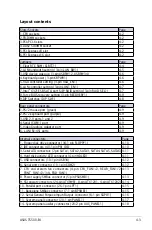


ASUS TS500-E4
4-17
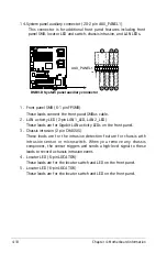
13. System panel connector (20-1 pin PANEL1)
This connector supports several chassis-mounted functions.
The system panel connector is color-coded for easy connection.
• System power LED (Green 3-pin PLED)
This 3-pin connector is for the system power LED. Connect the chassis
power LED cable to this connector. The system power LED lights up
when you turn on the system power, and blinks when the system is in
sleep mode.
• Hard disk drive activity LED (Red 2-pin IDE_LED)
This 2-pin connector is for the HDD Activity LED. Connect the HDD
Activity LED cable to this connector. The IDE LED lights up or flashes
when data is read from or written to the HDD.
• System warning speaker (Orange 4-pin SPEAKER)
This 4-pin connector is for the chassis-mounted system warning
speaker. The speaker allows you to hear system beeps and warnings.
• ATX power button/soft-off button (Yellow 2-pin PWRSW)
This connector is for the system power button. Pressing the power
button turns the system on or puts the system in sleep or soft-off
mode depending on the BIOS settings. Pressing the power switch for
more than four seconds while the system is ON turns the system OFF.
• Reset button (Blue 2-pin RESET)
This 2-pin connector is for the chassis-mounted reset button for system
reboot without turning off the system power.
DSBV
-D
DSBV-D System panel connector
PANEL1
MLED-
GND
NC
POWERBTN#
+5V
GND
GND
NC
P
NC
IDELED-
POWERLED- MLED+
NMIBTN#
GND
RESETBTN#
SPKROUT
GND
Summary of Contents for Pedestal/5U Rackmount Server TS500-E4 Server
Page 1: ...TS500 E4 Server Pedestal 5U Rackmount Server User s Manual ...
Page 12: ...xii ...
Page 76: ...Chapter 3 Installation option 3 ...
Page 136: ...5 42 Chapter 5 BIOS information ...
Page 176: ...6 40 Chapter 6 RAID configuration ...
Page 191: ...ASUS TS500 E4 7 15 8 Follow the screen instructions to complete installation ...
Page 196: ...7 20 Chapter 7 Driver installation ...
Page 202: ...Appendix Reference information A ...