


2-47
ASUS TS500-E4
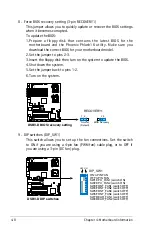
2.10.8 Power supply unit
Refer to this section when removing or installing a power supply unit to the
barebone system.
You MUST disconnect all power cable plugs from the motherboard and
other installed devices before removing the power supply unit.
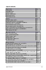
The picture below shows the motherboard and device connectors where
the power plugs are connected. Refer to the Appendix at the end of this
document for the power supply specifications.
2
1
3
Model PA4
1. 24-pin ATX (motherboard power
connector)
2. 4-pin +12V (motherboard power
connector, hidden behind the
cables)
3. 8-pin +12V (motherboard power)
4. 4-pin plug (optical drive)
5. 2 x 4-pin plugs (SATA backplane)
6. 4-pin plug (floppy disk drive,
hidden behind the backplane)
Model PX4
1. 24-pin ATX (motherboard power
connector)
2. 4-pin +12V (motherboard power
connector, hidden behind the
cables)
3. 8-pin +12V (motherboard power)
4. 4-pin plug (optical drive)
5. 2 x 4-pin plugs (SAS backplane)
6. 4-pin plug (floppy disk drive,
hidden behind the backplane)
5
6
Make sure to unplug ALL power cables from the system devices before
removing the power supply unit.
4
2
1
3
5
6
4
Summary of Contents for Pedestal/5U Rackmount Server TS500-E4 Server
Page 1: ...TS500 E4 Server Pedestal 5U Rackmount Server User s Manual ...
Page 12: ...xii ...
Page 76: ...Chapter 3 Installation option 3 ...
Page 136: ...5 42 Chapter 5 BIOS information ...
Page 176: ...6 40 Chapter 6 RAID configuration ...
Page 191: ...ASUS TS500 E4 7 15 8 Follow the screen instructions to complete installation ...
Page 196: ...7 20 Chapter 7 Driver installation ...
Page 202: ...Appendix Reference information A ...